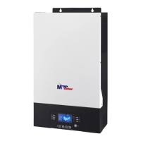
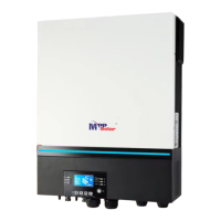
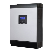
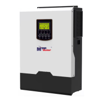
This document describes a multi-function inverter, combining the functions of an inverter, solar charger, and battery charger to provide uninterruptible power support. It features a comprehensive LCD display for user-configurable and easy-accessible button operations, allowing adjustments for battery charging current, AC or solar charging priority, and acceptable input voltage based on different applications.
Function Description
The inverter is designed to provide power for various appliances in home or office environments, including motor-type appliances like tube lights, fans, refrigerators, and air conditioners. It can operate with utility mains, a generator, or PV modules as input sources.
Basic System Architecture:
The inverter integrates into a hybrid power system, utilizing solar power, a generator (or utility), and external battery packs to supply power to home appliances.
Operating Modes:
- Standby Mode: The inverter is not turned on for AC output, but it can still charge batteries from PV energy or utility.
- Fault Mode: Indicates internal circuit errors or external issues such as over-temperature or output short circuits. In this mode, PV energy and utility can still charge batteries.
- Line Mode: The unit provides output power from the mains and charges the battery. If "solar first" is selected as the output source priority and solar energy is insufficient, both solar energy and utility will supply the loads and charge the battery.
- Battery Mode: The unit provides output power from the battery and/or PV power. If "solar first" is selected and the battery is not connected, solar energy and utility will provide the loads.
Important Technical Specifications
The manual provides detailed specifications across different operating modes:
Line Mode Specifications (Table 1):
- Input Voltage Waveform: Sinusoidal (utility or generator).
- Nominal Input Voltage: 230Vac.
- Low Loss Voltage: 170Vac±7V (UPS); 90Vac±7V (Appliances).
- Low Loss Return Voltage: 180Vac±7V (UPS); 100Vac±7V (Appliances).
- High Loss Voltage: 280Vac±7V.
- High Loss Return Voltage: 270Vac±7V.
- Max AC Input Voltage: 300Vac.
- Nominal Input Frequency: 50Hz / 60Hz (Auto detection).
- Low Loss Frequency: 40±1Hz.
- Low Loss Return Frequency: 42±1Hz.
- High Loss Frequency: 65±1Hz.
- High Loss Return Frequency: 63±1Hz.
- Output Short Circuit Protection: Circuit Breaker.
- Efficiency (Line Mode): >95% (Rated R load, battery full charged).
- Transfer Time: 10ms typical (UPS); 20ms typical (Appliances).
- Output Power Derating: When AC input voltage drops to 170V, the output power will be derated.
Inverter Mode Specifications (Table 2):
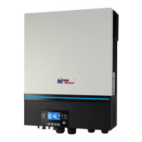
- Models: PIP3624MT (3.6KVA/3.6KW) and PIP5648MT (5.6KVA/5.6KW).
- Output Voltage Waveform: Pure Sine Wave.
- Output Voltage Regulation: 230Vac±5%.
- Output Frequency: 50Hz.
- Peak Efficiency: 93%.
- Overload Protection: 5s@≥130% load; 10s@105%~130% load.
- Surge Capacity: 2* rated power for 5 seconds.
- Nominal DC Input Voltage: 24Vdc (PIP3624MT) / 48Vdc (PIP5648MT).
- Cold Start Voltage: 23.0Vdc (PIP3624MT) / 46.0Vdc (PIP5648MT).
- Low DC Warning Voltage (@load < 50%): 23.0Vdc (PIP3624MT) / 46.0Vdc (PIP5648MT).
- Low DC Warning Voltage (@load ≥ 50%): 22.0Vdc (PIP3624MT) / 44.0Vdc (PIP5648MT).
- Low DC Warning Return Voltage (@load < 50%): 23.5Vdc (PIP3624MT) / 47.0Vdc (PIP5648MT).
- Low DC Warning Return Voltage (@load ≥ 50%): 23.0Vdc (PIP3624MT) / 46.0Vdc (PIP5648MT).
- Low DC Cut-off Voltage (@load < 50%): 21.5Vdc (PIP3624MT) / 43.0Vdc (PIP5648MT).
- Low DC Cut-off Voltage (@load ≥ 50%): 21.0Vdc (PIP3624MT) / 42.0Vdc (PIP5648MT).
- High DC Recovery Voltage: 32Vdc (PIP3624MT) / 62Vdc (PIP5648MT).
- High DC Cut-off Voltage: 33Vdc (PIP3624MT) / 63Vdc (PIP5648MT).
- No Load Power Consumption: <40W (PIP3624MT) / <55W (PIP5648MT).
Charge Mode Specifications (Table 3):
- Utility Charging Mode:
- Charging Current (UPS): 100Amp (@V_IP=230Vac).
- Bulk Charging Voltage (Flooded Battery): 29.2Vdc (PIP3624MT) / 58.4Vdc (PIP5648MT).
- Bulk Charging Voltage (AGM / Gel Battery): 28.2Vdc (PIP3624MT) / 56.4Vdc (PIP5648MT).
- Floating Charging Voltage: 27Vdc (PIP3624MT) / 54Vdc (PIP5648MT).
- Charging Algorithm: 3-Step (Bulk, Absorption, Float).
- Solar Input:
- Max. PV Array Power: 5000W (PIP3624MT) / 6000W (PIP5648MT).
- Max. PV Current: 27A.
- Nominal PV Voltage: 320Vdc (PIP3624MT) / 360Vdc (PIP5648MT).
- Start-up Voltage: 60Vdc +/- 10Vdc.
- PV Array MPPT Voltage Range: 60~450Vdc.
- Max. PV Array Open Circuit Voltage: 500Vdc.
- Max Charging Current (AC charger plus solar charger): 120Amp.
General Specifications (Table 4):
- Operating Temperature Range: -10°C to 50°C.
- Storage Temperature: -15°C ~ 60°C.
- Humidity: 5% to 95% Relative Humidity (Non-condensing).
- Dimension (D*W*H), mm: 107 x 322.6 x 420.3.
- Net Weight, kg: 9.5 (PIP3624MT) / 10.5 (PIP5648MT).
Usage Features
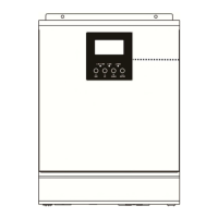
User Interface:
- LCD Display: Shows operating status, input/output power information, battery level, load level, and various icons indicating connections (AC, PV), operational modes (Bypass, Inverter, Utility Charger), and alarms.
- Function Buttons: Four touchable buttons with status indication for navigation (UP, DOWN, ESC, ENTER) and confirming selections in setting mode.
- LED Indicators: Green (Solid On: normal operation; Alternating Flashing with Yellow: battery charging), Yellow (Solid On: warning), Red (Solid On: fault mode).
Configurable Settings (via LCD Setting Programs):
- Output Source Priority (Program 01): Utility first, Solar first, SBU priority (Solar-Battery-Utility).
- Maximum Charging Current (Program 02): Configurable from 10A to 120A (default 60A).
- AC Input Voltage Range (Program 03): Appliances (default) or UPS.
- Battery Type (Program 05): AGM (default), Flooded, User-Defined.
- Auto Restart (Programs 06 & 07): Enable/disable auto restart for overload and over-temperature.
- Output Frequency (Program 09): 50Hz (default) or 60Hz.
- Output Voltage (Program 10): 220V, 230V (default), 240V.
- Maximum Utility Charging Current (Program 11): Configurable from 2A to 100A (default 30A).
- Voltage Point Back to Utility Source (Program 12): Configurable for SBU priority.
- Voltage Point Back to Battery Mode (Program 13): Configurable for SBU priority.
- Charger Source Priority (Program 16): Utility first, Solar first, Solar and Utility, Only Solar.
- Alarm Control (Program 18): Alarm on (default) or off.
- Auto Return to Default Display Screen (Program 19): Enable (default) or stay at latest screen.
- Backlight Control (Program 20): Backlight on (default) or off.
- Beeps while Primary Source is Interrupted (Program 22): Alarm on (default) or off.
- Overload Bypass (Program 23): Bypass disable (default) or enable.
- Record Fault Code (Program 25): Record enable (default) or disable.
- Bulk Charging Voltage (Program 26): Default 28.2V (PIP3624MT) / 56.4V (PIP5648MT), configurable for user-defined battery type.
- Floating Charging Voltage (Program 27): Default 27.0V (PIP3624MT) / 54.0V (PIP5648MT), configurable for user-defined battery type.
- Low DC Cut-off Voltage (Program 29): Default 21.0V (PIP3624MT) / 42.0V (PIP5648MT), configurable for user-defined battery type.
- Battery Equalization (Program 30): Enable (default) or disable.
- Battery Equalization Voltage (Program 31): Default 29.2V (PIP3624MT) / 58.4V (PIP5648MT), configurable for user-defined battery type.
- Battery Equalized Time (Program 33): Default 60min, configurable from 5min to 900min.
- Battery Equalized Timeout (Program 34): Default 120min, configurable from 5min to 900min.
- Equalization Interval (Program 35): Default 30 days, configurable from 0 to 90 days.
- Equalization Activated Immediately (Program 36): Enable or disable.
- Low DC Cut-off Voltage on Second Output (Program 60): Default 21.0V (PIP3624MT) / 42.0V (PIP5648MT), configurable for user-defined battery type.
- Setting Discharge Time on the Second Output (Program 61): Disable (default) or configurable from 0 to 990 min.
Battery Equalization Description:
This function reverses the buildup of negative chemical effects like stratification and helps remove sulfate crystals from battery plates, extending battery life.
- Activation: Enabled via LCD setting Program 30, then either by setting an equalization interval (Program 35) or activating immediately (Program 36).
- When to Equalize: Initiates in the floating charge stage when the equalization interval is reached or activated immediately.
- Charging and Timeout: The controller charges the battery until it reaches the equalization voltage, then maintains this voltage until the equalization timer runs out. If the battery voltage doesn't recover to the equalization point, the charge controller extends the time.
Maintenance Features
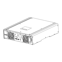
Clearance and Maintenance for Anti-Dust Kit:
- Overview: The inverter is equipped with an anti-dust kit to adjust internal temperature and improve reliability in harsh environments.
- Clearance and Maintenance Steps:
- Loosen the screw on the side of the inverter.
- Remove the dustproof case and air filter foam.
- Clean the air filter foam and dustproof case.
- Re-assemble the dust-kit back to the inverter.
- Notice: The anti-dust kit should be cleaned every one month.
Troubleshooting:
The manual includes a comprehensive troubleshooting table with common problems, LCD/LED/Buzzer indications, possible causes, and recommended actions. Examples include:
- Unit shuts down automatically during startup: Battery voltage too low (<1.91V/cell) or internal fuse tripped. Actions: Re-charge battery, replace battery, contact repair center.
- No response after power on: Battery voltage too far low, internal fuse tripped, input protector tripped. Actions: Replace battery, contact repair center.
- Mains exist but unit works in battery mode: Insufficient quality of AC power, "SUB" (Solar first) priority selected. Actions: Check AC wires, check generator, change output source priority.
- When unit is turned on, internal relay is switched on and off repeatedly: Battery is disconnected. Action: Check battery wires.
- Buzzer beeps continuously and red LED is on (Fault Mode):
- Fault 07 (Overload time out): Overload error. Action: Reduce connected load.
- Fault 05 (Output short circuited or over temperature): Output short circuited, internal converter temperature over 120°C. Action: Check wiring, check air flow, reduce ambient temperature.
- Fault 02 (Over temperature): Inverter temperature over 100°C. Action: Reduce ambient temperature.
- Fault 03 (Battery is over-charged): Battery voltage too high. Action: Return to repair center, check battery spec.
- Fault 01 (Fan fault): Fan locked. Action: Replace fan.
- Fault 06/58 (Output abnormal): Inverter voltage below 190Vac or higher than 260Vac. Action: Reduce the connected load, return to repair center.
- Fault 08/09/53/57 (Internal components failed): Action: Return to repair center.
- Fault 51 (Over current or surge): Action: Restart unit, if error persists, return to repair center.
- Fault 52 (Bus voltage is too low): Action: Return to repair center.
- Fault 55 (Output voltage is unbalanced): Action: Return to repair center.
- Fault 59 (PV input voltage is beyond the specification): Action: Reduce number of PV modules in series.
Safety Instructions:
The manual emphasizes critical safety instructions, including reading all warnings, not disassembling the unit, disconnecting all wirings before maintenance, using only deep-cycle lead acid batteries, and ensuring proper grounding and cable sizing. It also warns against connecting grounded PV modules to non-isolated inverters and recommends using PV junction boxes with surge protection.