11
● connect soalr module positive(+) wire to the positive terminal of the unit and soalr
module negative(-) wire to the negative terminal of the unit. Use #6 to #7 AWG wire
rated for 75º C for Solar connections.
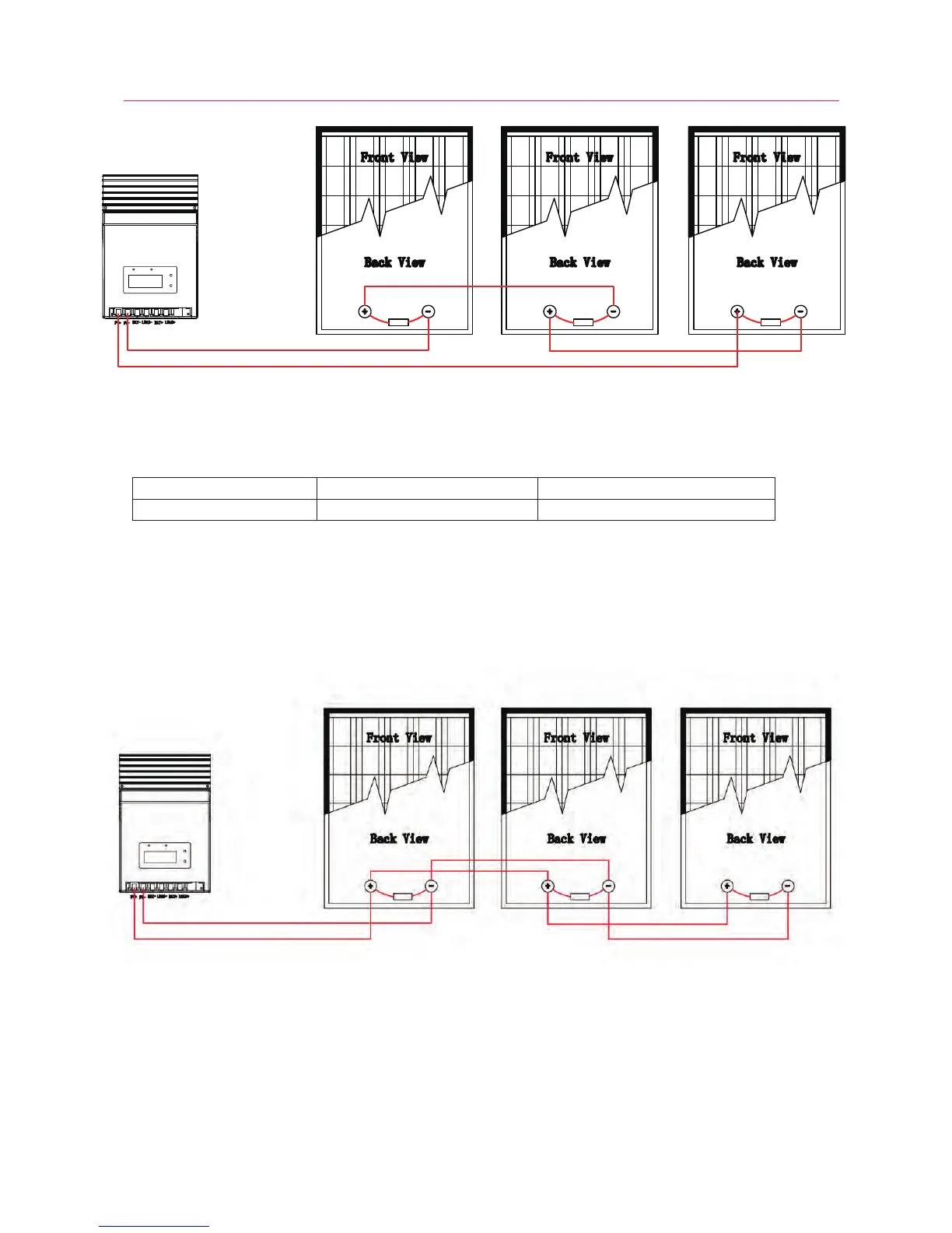
Figure 3-7. Solar modules in series connection
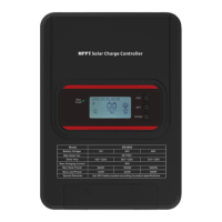
Model Nominal DC Voltage Maximum Solar Module Power
MPPT-4015A 12/24 VDC 560/1120 W
2) Multiple solar modules in parallel connection(Refer to Fig.7): Each module’s voltage
must be equal to the nominal DC Voltage of the unit. The sum of their solar power must
exceed the maximum capacity of the unit(see below Table 3-1)
Step 5: Switch on DC breaker or install DC fuse
After completing all wires,double check if all wires are connected well. Then switch on DC
breaker or install DC fuse on. Take off the cover of solar module. When the solar module power
is above 15V, the charge will automatically turn on to work.
Table 3-1 Maximum solar module power
Figure 3-8. Solar modules in parallel connection