Step 2: DC load Wiring
WARNING:
Please use the appropriate cable size according to load rating. Please refer to
important Safety Warnings Section for the details. It will prevent internal high temperature.
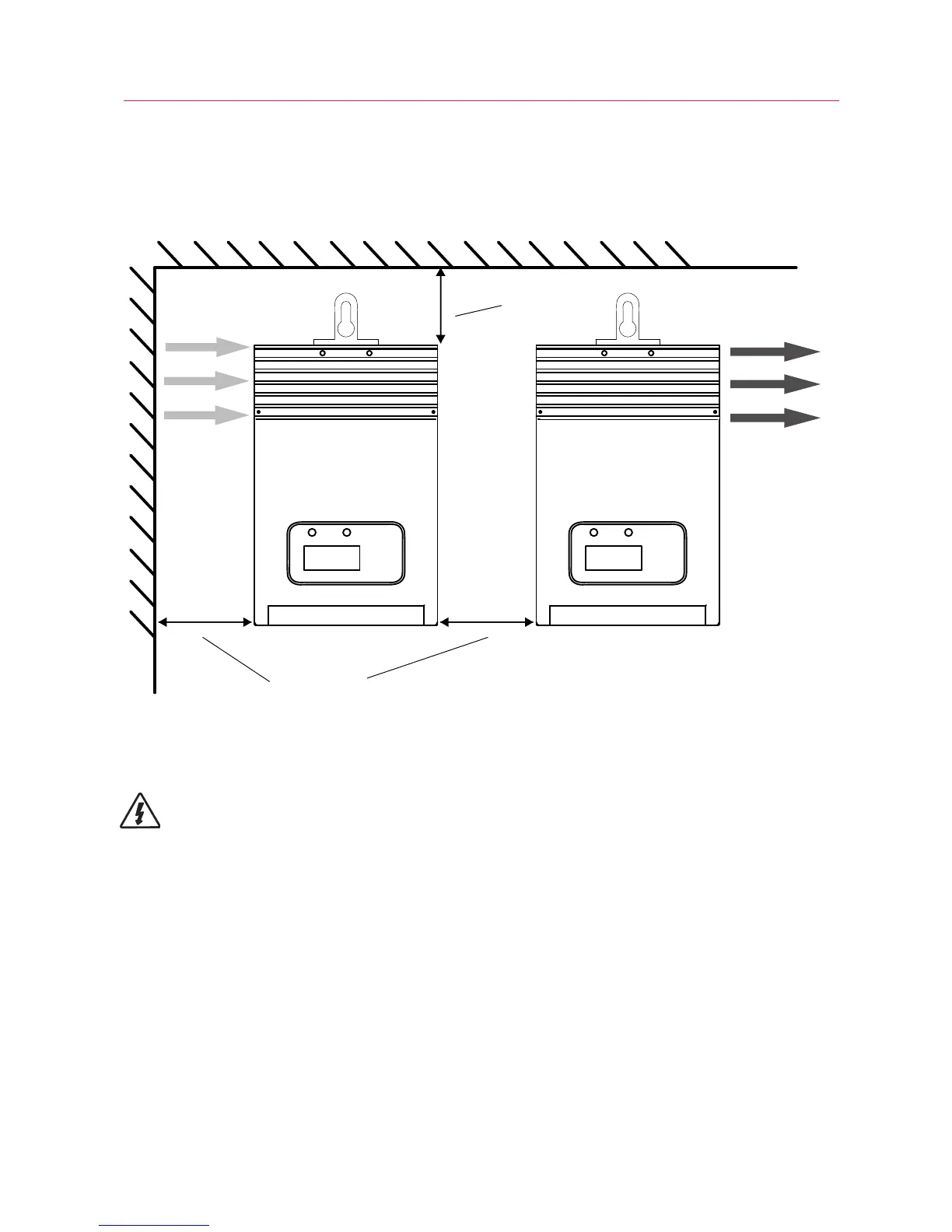
1. Attach the mounting hanger to the bottom of the MPPT with the M6 screw
provided as shown in figure 3-1.
2. Place the MPPT on a vertical surface protected from direct sunlight, high
temperatures, and water. The MPPT requires at least 150 mm of clearance
right and left. flow as shown in figure 3-2 below.
AT LEAST
200mm
AT LEAST
200mm
COOL
AIR
WARM
AIR
Figure 3-2. Required mounting clearance for air flow.
8
The load output will provide battery voltage to connected loads such as lights,monitors and
other electronic devices.
● connect load positive(+) wire to the positive terminal of the unit and load negative(-) wire
to the negative terminal of the unit.
● install a DC Breaker or a DC fuse holder in a positive wire. The rating of the DC Breaker/
Fuse must be rated to 125% of the maximum load current or more. Keep the DC breaker off or
do not install the DC fuse.
● See Section 4.3 Setting Operation for more detials about load control.