PAGE 22 — DCA25SSIU4F 60 HZ GENERATOR • OPERATION MANUAL — REV. #4 (01/17/18)
GENERATOR OUTPUTS
GENERATOR OUTPUT VOLTAGES
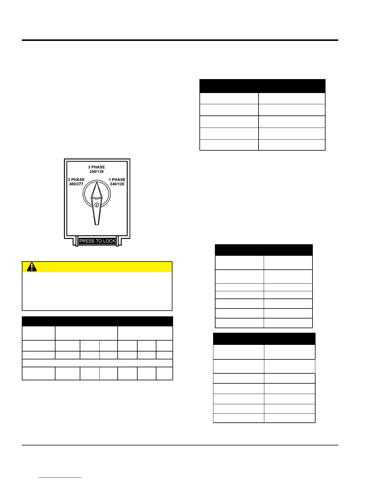
A wide range of voltages are available to supply voltage for
many different applications. Voltages are selected by using
the voltage selector switch (Figure 12). To obtain some of
the voltages as listed in Table 7 (see below) will require a
fine adjustment using the voltage regulator (VR) control
knob located on the control panel.
Voltage Selector Switch
The voltage selector switch (Figure 12 is located above the
output terminal panel’s Hard Wire Hook-up Panel. It has
been provided for ease of voltage selection..
Figure 12. Voltage Selector Switch
CAUTION
NEVER change the position of the voltage selector
switch while the engine is running. ALWAYS place
circuit breaker in the OFF position before selecting
voltage.
Table 7. Voltages Available
UVWO Output
Terminal Lugs
Voltage Selector Switch
3-Phase 240/139V Position
Voltage Selector Switch
3-Phase 480/270V Position
3Ø
Line-Line
208V 220V 240V 416V 440V 480V
1Ø Line-Neutral 120V 127V 139V 240V 254V 277V
Voltage Selector Switch Single-Phase 240/120V Position
1Ø Line-Neutral/
Line-Line
120V
Line-Neutral
N/A N/A
240V
Line-Line
N/A N/A
Maximum Amps
Table 8 shows the maximum amps the generator can
provide. DO NOT exceed the maximum amps as listed.
GFCI Receptacle Load Capability
The load capability of the GFCI receptacles is directly
related to the voltage being supplied at either the output
terminals or the three twist lock auxiliary receptacles.
Figure 15 and Table 10 show what amount of current is
available at the GFCI receptacles when the output terminals
and twist lock receptacles are in use. Be careful that your
load does not to exceed the available current capability at
the receptacles.
Table 8. Generator Maximum Amps
Rated Voltage Maximum Amps
1Ø 120 Volt 55.6 amps (4 wire)
1Ø 240 Volt 27.8 amps (4 wire)
3Ø 240 Volt 60 amps
3Ø 480 Volt 30 amps
Table 9. 1Ø GFCI Receptacle Load Capacity
KW in Use
Twist Lock (C6369)
Available Load
Current (Amps)
1Ø 240/120V
GFCI Duplex
5-20R 120V
25 0
20.8 5 amps/receptacle
16.7 10 amps/receptacle
12.5 15 amps/receptacle
8.4 20 amps/receptacle
Table 10. 3Ø Generator Maximum Amps
KVA in Use
(UVWO Terminals)
Available Load
Current (Amps)
3Ø 240/480V
GFCI Duplex
5-20R 120V
70
0 amps/receptacle
65.8
5 amps/receptacle
61.7
10 amps/receptacle
57.5
15 amps/receptacle
53.4
20 amps/receptacle