Mr
Steam
®
Installation, Operation & Maintenance Manual
Select a location as near as practical to the steam room.Typical locations include: closet, vanity cabinet, heated attic or basement.
1.
Locate steambath generator within 25 feet of steam room.
2.
Do not install steambath generator inside steam room.
3.
Do not
install steambath generator outdoors or wherever environmental conditions may affect the safety and/or
performance of the generator.
4.
Do not install steambath generator in unheated attic or any locations where water could freeze.
5.
Do not
install steambath generator near flammable or corrosive materials or chemicals such as gasoline, paint thinners, or
the like. Installation in areas having high concentrations of chlorine (such as pool equipment room) must be avoided.
6.
Install steambath generator on a solid and level surface.
7.
Install steambath generator in an upright position only.
8.
Install anti-water hammer device as required.
9.
Provide a minimum of (12) inches to both ends and top of the steam generator or as required for servicing. See page (5).
10.
Provide unions as required to facilitate installation and disconnection of piping.
11. IMPORTANT:
Steam line, safety valve
, drain valve, plumbing and steamheads become hot during operation and remain
hot after shutdown for a period of time. Provide appropriate protection, including insulating plumbing lines. Avoid plumbing
runs and steamhead locations that can come in contact with bathers.
12.
MrSteam controls can be located inside the steam room or on the outside of the steam room.
See separate CONTROL INSTALLATION AND OPERATION INSTRUCTIONS for specific details. If the controls are
located outside the steamroom, a remote sensor (part number MSTS) is required.
NOTE: The TEMPO series controls are suitable for use with UL Listed MrSteam generators and for use in a wet environment.
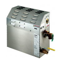
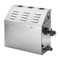
The MS series of steam generators are for residential use only. Commercial or other
non-residential applications void the warranty and may adversely affect product performance.
Use only MrSteam TEMPO series controls.
Locating the Steam Generator Unit
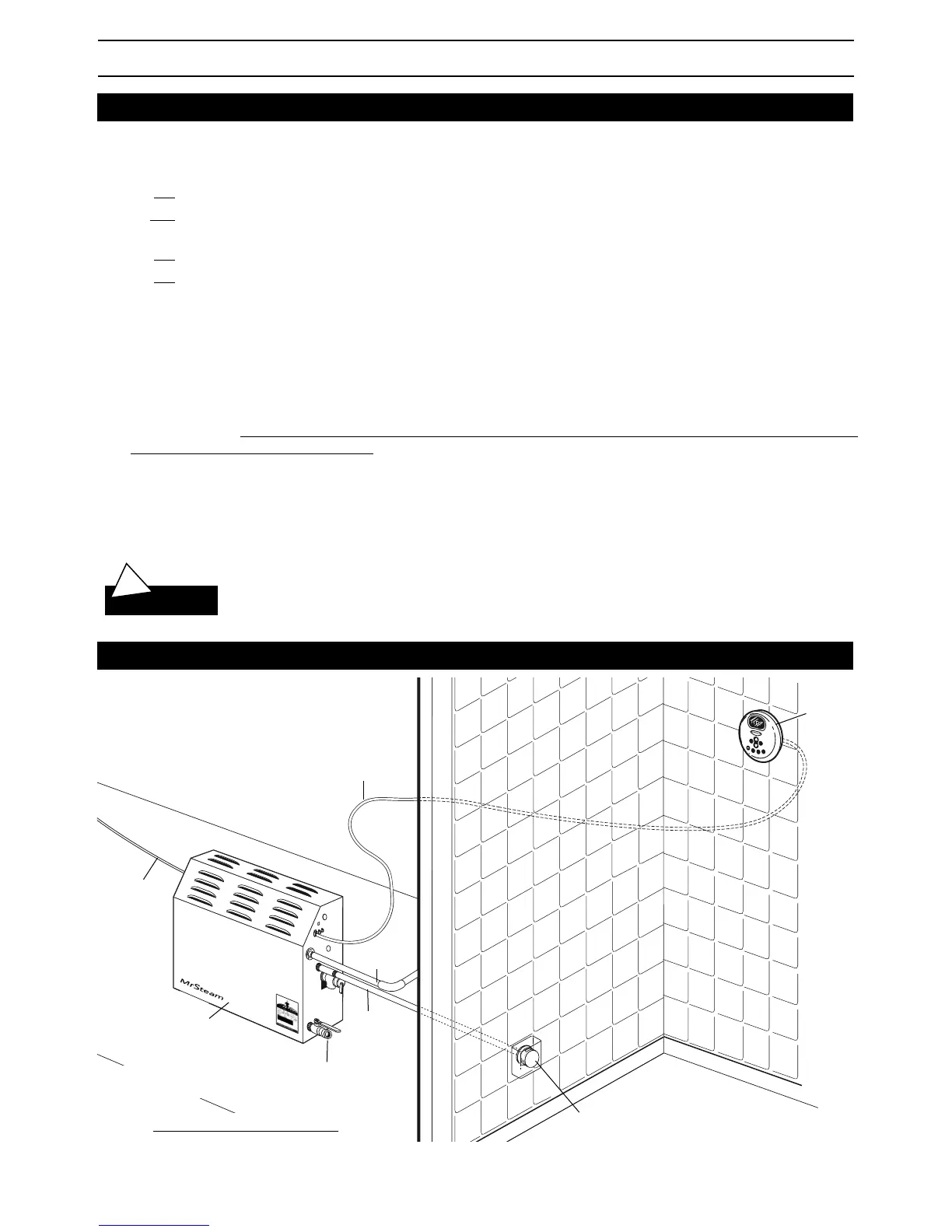
Typical MrSteam Installation
2
!
WARNING
NOTE:
For illustrative purposes only.
Consult with qualified designer, architect or
contractor for steam room construction details.
Provide unions as required to facilitate
installation and disconnect of piping
Steam generator
Field installed
power supply
Field installed
steam supply pipe
Valve is
shown open
Control cable
Steam Head (shown with optional acrylic shield)
See page 4 for Steam Head Installation information
TEMPO
®
or
TEMPO/PLUS
®
Control
See Control Manual for
installation information
Field installed
water supply pipe
 Loading...