MrSteam
®
Installation, Operation & Maintenance Manual
Plumbing
All plumbing shall be performed by a qualified licnesed plumber and in accordance with applicable National and local codes.
• Use unions on all pipe connections.
• Use only brass piping or copper tubing
• Do not use black, galvanized or PVC pipe.
Water Supply (3/8” NPT)
1.
Connect hot or cold water line. Hot water line is preferable, however hot water should not exceed 160° F.
2.
Provide a shut off valve in the water supply line upstream of the steambath generator.
3.
Do not overheat inlet solenoid valve with solder connections. Overheating will damage parts.
4.
Flush inlet water line thoroughly before making connection to unit.
5.
Strainer recommended upstream of feed water connection.
6.
For best performance water pressure should be 15 to 20 PSIG. Reduce pressure as required if necessary.
7.
Provide anti-water hammer device as required.
Steam Outlet (1/2” NPT)
1.
Do not install a valve in steam line. Flow of steam must be unobstructed.
2.
Use 1/2-inch brass pipe or copper tubing from unit to steam head.
3.
Insulate steam line using pipe insulation rated 250° F or higher.
4.
Pitch steam line 1/4" per foot towards steam head or steam generator to avoid valleys and trapping of condensate.
NOTE:
Running the steam line down and then up will create a steam trap blocking the flow of steam.
Steam Head (1/2” NPT)
INSTALLER: Because the steam head and direct steam emissions are very hot, locate the steam head
where incidental contact by bather with the steam head or direct steam emission cannot occur.
1.
Locate steam head 6-12 inches above floor, except for
•
Tub/shower enclosures, install 6 inches above tub top edge.
•
For enclosures with acrylic or other non-heat resistant flooring
install Acrylic Shield Part Number MS-103412.
2.
Install steam head with steam slot facing downward.
IMPORTANT:
To preserve steam head finish, do not use wrench
or other tools to tighten. Hand tightening is sufficient when
Teflon or equal pipe thread sealing compound is used. Use no
abrasive cleansers or chemicals. Use only mild soap and sponge.
3.
IMPORTANT:
Consult with supplier of acrylic, fiberglass
and other non-heat resistant enclosures for recommended
steam head location.
Drain (1/2” NPT)
NOTE:
A drain valve is provided to facilitate servicing. Provide a
drain line connection from steambath generator drain valve accord-
ing to National and local Codes. Check local plumbing code for
receptor, trap and vent requirements. Unit drains by gravity.
Safety Valve (3/4” NPT)
Where permitted by local codes, provide an outlet plumbing connection for safety valve.
To insure proper and automatic safety valve operation: DO NOT connect a shut off valve or a plug
at safety valve outlet. DO NOT connect a shut off valve in steam supply pipe.
Installation
4
!
WARNING
!
CAUTION
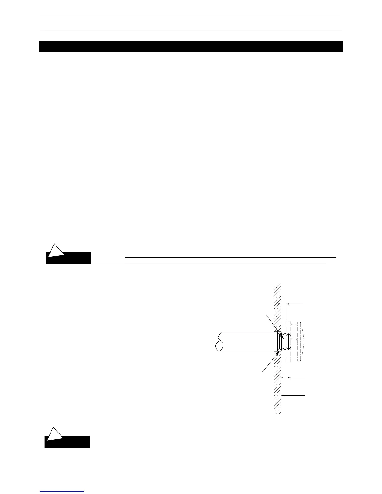
Steam Supply Pipe
Steam Head
1/2" (without Acrylic Shield)
3/4" (with Acrylic Shield)
1/4" minimum clearance required
when Acrylic Shield (PN 103412) is
used. See installation instructions
provided with the Acrylic Shield.
Fill gap with silicone or
equal sealant as required
for moisture seal.
Finished interior face
of steam room wall
Use Teflon or equal
sealant on pipe threads
 Loading...