EasyManuals Logo

mr. steam MS-65T Installation Operation & Maintenance

mr. steam MS-65T
15 pages
To Next Page IconTo Next Page
To Previous Page IconTo Previous Page
Page #9 background imageLoading...
Page #9 background image
Installation Instructions for Models:
MS-Super 4T, MS-Super 5T and MS-Super 6T
1.
Install each unit as in a single installation as close to each other as possible.
2. IMPORTANT
Power must be disconnected at the main electrical supply. Remove steam generator covers.
3.
Connect the TEMPO/PLUS control to either unit per instructions supplied
with the TEMPO/PLUS control.
4.
Remove one knock-out on each generator as shown. Insert the ends of interconnecting cable provided
(PN 103904) through the knock-outs as shown in diagram A, page 3. Connect each end to the printed
circuit board as shown.
5.
Connect separate plumbing and power supplies for each unit.
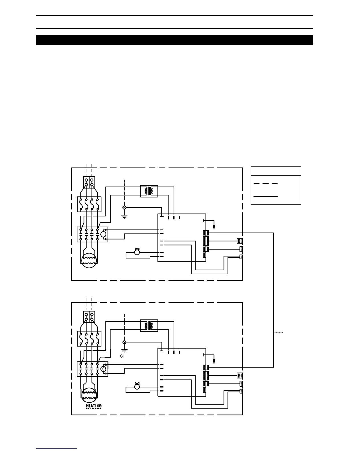
Single Phase Wiring Diagram
with TEMPO
/
PLUS control
MrSteam
®
Installation, Operation & Maintenance Manual
9
HEATING
ELEMENT
CONTROL BOARD
CONTACTO
R
ROU
N
D
WATER
FEED
SOLENOID
VALVE
ELEMENT
S
L1 L2
PURPLE
WHITE
LIGHT
BLUE
GRAY
WHITE
G
GREEN
BLACK
BLACK
WHITE
DARK
BLUE
TO PROBE
AUTOFLUSH (optional)
TANDEM
CABLE
103904
CONTROL BOARD
GROUND
FUSES
CONTACTOR
C
S
G
POWER INPUT
POWER INPUT
L2L1
LIGHT
BLUE
WHITE
PURPLE
GREEN
WHITE
GRAY
BLACK
BLACK
WHITE
DARK
BLUE
TRANSFORMER
TO PROBE
TEMPO/EXT
(optional)
TEMPO/PLUS
AUTOFLUSH
(optional)
TRANSFORMER
WATER
FEED
SOLENOID
VALVE
FUSES
CABLE
CABLE
CABLE
CABLE
FACTORY
WIRING
FIELD
WIRING
LEGEND
(All Diagrams)
Wiring Diagram: MS-Super 4T, MS-Super 5T,
MS-Super 6T Single Phase Models
NOTE:
Cable length is 12 feet

Other manuals for mr. steam MS-65T

Questions and Answers:

Question and Answer IconNeed help?

Do you have a question about the mr. steam MS-65T and is the answer not in the manual?

mr. steam MS-65T Specifications

General IconGeneral
Brandmr. steam
ModelMS-65T
CategoryIron
LanguageEnglish

Related product manuals