mr
.
steam
®
Installation, Operation & Maintenance Manuals
______________________________________________________________________________
I N S T A L L E R
16
TROUBLESHOOTING
Applies to 1-2
1. Electric shock hazard. MrSteam steam generators are connected to high voltage and
contain live electrical components. All installation and service to be performed by
qualified and licensed electricians only. Installation or service by unqualified persons
or failure to use MrSteam parts may result in property damage or in a personal injury.
2. Do not disassemble or service any components. Internal components contain no
serviceable parts.
The model and serial
number is printed on the data plate on
the front of the steam bath generator.
Please have this information available
when contacting Technical Services.
Note: Disconnect all connections
going to the steam generator.
When disconnecting the AutoFlush
connector, close manual drain valve.
Step 1 Check main incoming
power to the unit.
Step 2 Ensure the black wires from the primary side
of the transformer are connected to the quick con-
nect tabs on the line side of the contactor.
Step 3 Verify that 24 VAC is coming
out of the transformer, WHITE & WHITE/BLUE wires,
into the circuit board.
Step 4 Verify that the green light
on the Circuit Board is ON.
Step 5 Push the white Force-On test button on the
circuit board (see page 17) to run the generator for
a 10 minute test cycle. Make sure the steam room
is empty.
Step 6 Verify 24 VAC to the water feed solenoid,
GRAY & WHITE/GRAY wires (will fill when needed).
Step 7 Temporarily short out the WLS (Purple wire)
and GROUND (Green wire) terminals and verify that
the contactor engages.
Step 8 When the red light is ON, verify 24 VAC,
RED & WHITE/RED wires, to the contactor.
Step 9 Check main voltage on the load side of the
contactor when it is engaged.
Step 10 If all steps on the power path were verified,
turn OFF power to the unit.
Step 11 Using multimeter, check the resistance
(ohms) of each heating element test point, as shown
in Resistance Range Chart.
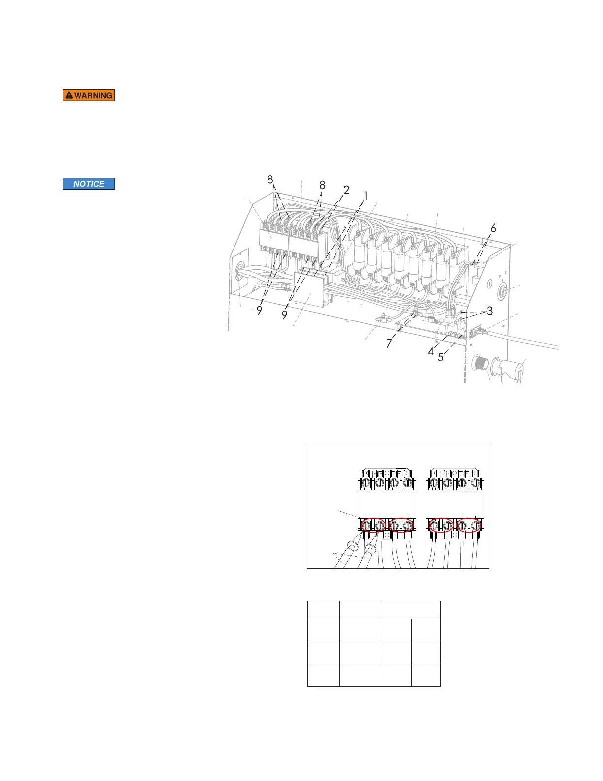
Safety Valve
Primary
T
ransformer
Secondary
Transformer
F
uses Control Board
W
ater Feed
Solenoid
Steam
Outlet
L
iquid
Level Probe
P
lug and Play
C
onnection
Primary
Contactor
Secondary
Contactor
Power
Supply
Knock-Out
P
ower Block
W
ater Inlet
Model Resistance
No. Voltage (V) Range (Ohms)
MX4E
208 7.8 9.5
240 10.4 12.7
MX5E
208 6.5 7.9
240 8.6 10.6
MX6E
208 5.2 6.3
240 6.9 8.4
Secondary
Contactor
Heating
Element Test
Points
Multimeter
Probes
Primary
Contactor
The steam generator represented in this illustra-
tion is for reference purposes only. Please con-
tact MrSteam for specific product information.
Resistance Range Char t
Contactor Test Points