64
Appendix
GB
Model 9010/9020 SIL
12.5 4-20 mA Transmitter Connections
Control Units 9010 SIL and 9020 SIL can accept, respectively, one or two input signals originating
from transmitters. These transmitters, with a 4-20 mA circuit will have to have the right CE (EU)
type certificate and will have to conform to Section 1.5 of Attachment II of Directive 2014/34/EU.
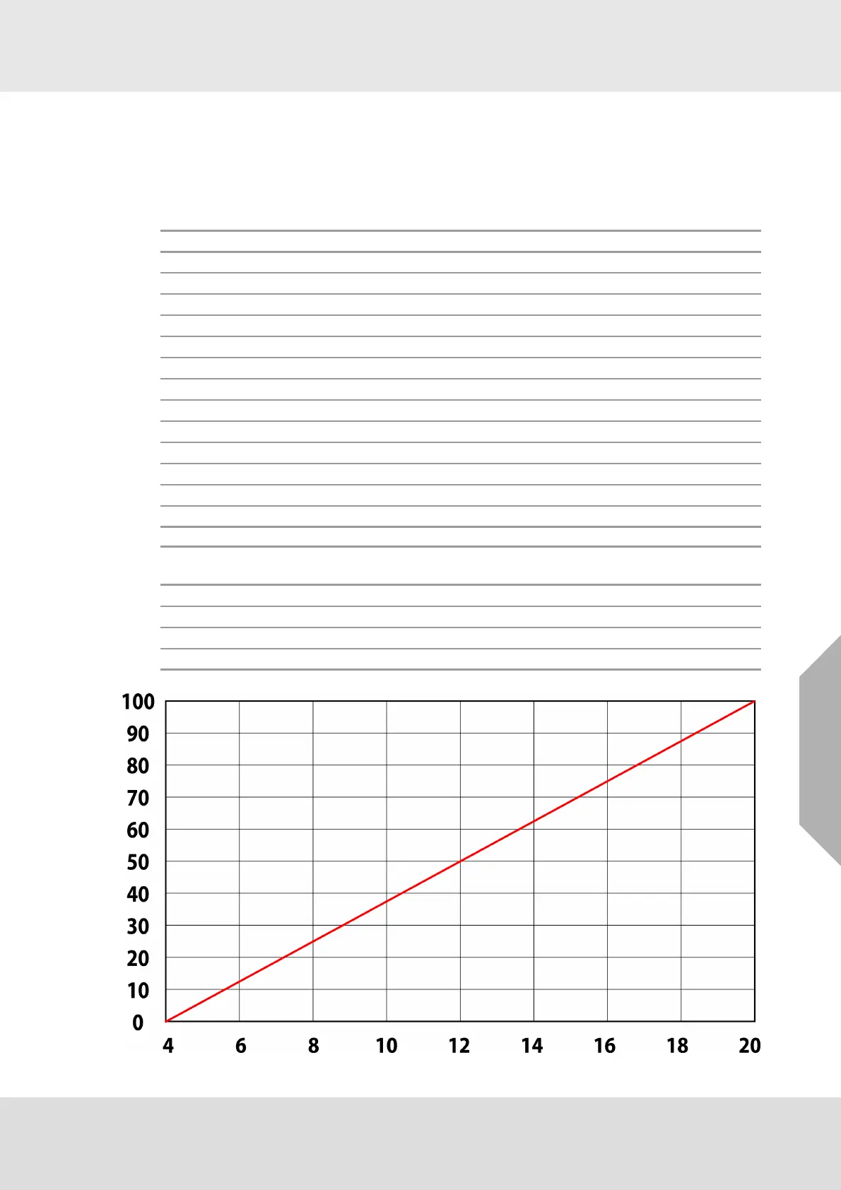
Control unit channels A and B configured for an input signal of 4-20 mA
Measurement range 0-100 % LEL
Fig. 19 Response curve for mA input (Equal for both Channel A and Channel B)
Input4/20 mA Theoretical reading Display reading 9010/9020 SIL Module
Ch A Ch B
2 -12,5 -d1 -d1
4000
6 12,5 12 12
8252525
10 37,5 37 37
12 50 50 50
14 62,5 62 62
16 75 75 75
18 87,5 87 87
20 100 100 100
21 106,3 EEEE EEEE
22 112,5 EEEE EEEE
Input signal
(mA)
C / W/ A Horn Failure
2 in normal state in normal state activated
4-20 depends on alarm setting activated with a new alarm activated with a new failure
21 activated activated activated
22 activated activated activated