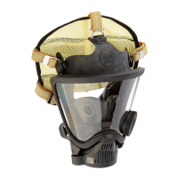
FIREHAWK M7 SECOND STAGE REGULATOR
Inspection of the Valve Fork for Proper Height
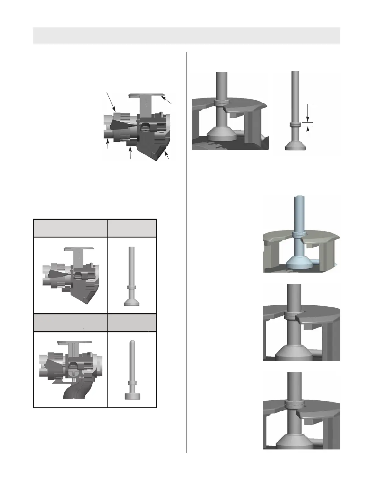
Inspect and adjust valve fork height with the valve fork
pointing toward you. The valve fork assembly must move
up and down freely.
1. Press the top of the
valve fork to check
movement.
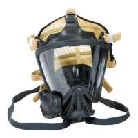
2. Use the Height Gauge to verify the fork height setting.
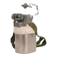
Note: Firehawk regulators use one of two valve assem-
blies: P/N 10090458 or P/N 10030664. Use the appropri-
ate Gauge.
*See Firehawk M7 Second Stage Regulator
Replacement and Overhaul Kits/Height Gauge Kits for
ordering information.
3. Center the Gauge in the valve fork.
Note: Ensure that the valve assembly is vertical and can
move freely.
4. The top of the valve fork must be within the accept-
able range.
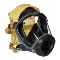
Acceptable Valve Fork Heights
Nominal height – Top of
fork level with center of
acceptable range.
Maximum Height – Top of
fork level with top of
acceptable range.
Minimum Height – Top of
fork level with bottom of
acceptable range.
7
TAL 114 (L) Rev. 7 - 10093086
If your valve assembly looks like this:
If your valve assembly looks like this
Acceptable
range
Valve Assembly Height Gauge*
PN 10087295 PN 10090457
Valve Assembly Height Gauge*
PN 10030664 PN 10050146
Adjustment Wheel
Fork
Valve Locking Tab
Valve Housing
Valve
Support