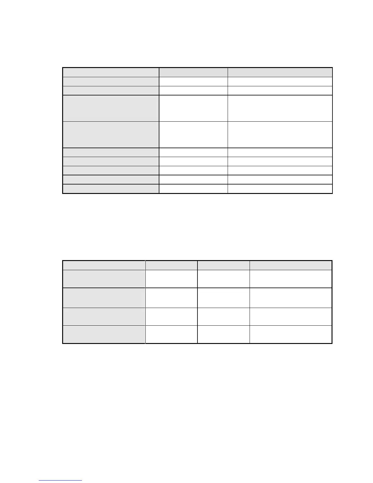
Table 5: Miscellaneous
0 = Sampling
1 = Manual Calibration
2 = Auto-Standardization
0 = Sampling
1 = Manual Calibration
2 = Auto-Standardization
Uncorrected, scaled, continuous
Uncorrected, scaled, continuous
Uncorrected, scaled, continuous
Uncorrected, scaled, continuous
* Gas sensor levels for each point among the active sensors use a pair of consecutive
addresses. They are compliant with the IEEE 754 Floating Point format that is 32 bit
single precision. One decimal place is passed through the gateway.
Table 6: Common Alarming
Fixed/Non-failsafe
0=Open 1=Closed
Fixed/failsafe
0=Closed 1=Open
Default Non-failsafe*
0=Open 1=Closed
Default Non-failsafe*
0=Open 1=Closed
* User Changeable Parameter - State may need to be reversed depending on usage.
 Loading...


