44
3103-1001 Rev. 0
4.2.3 Set-points
The set-point screen is used to enter trouble, warning, and alarm set-points for each sensor per point.
All 12 set-point screens take the same form except for the screen titles and the data within them. A
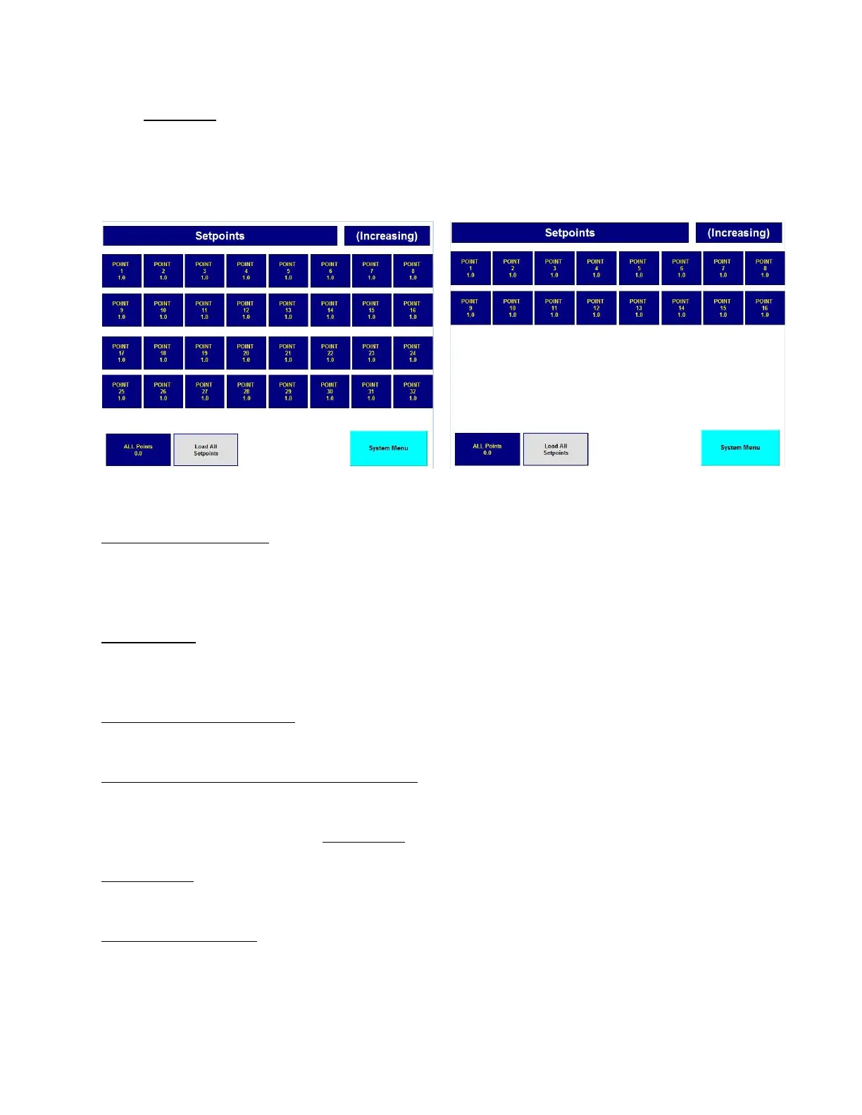
typical set-point screen is shown below.
Figure 23: Sensor Set-Point Figure 24: Sensor Set-Point (Dual)
"S1 ALARM Set points" - This is the screen title and is a multistage message indicator. This
indicator has 12 messages corresponding to trouble, warning, and alarm for sensors 1-4. It states
what set points are represented by the data on the screen. The screen title will also match the button
legend that was pushed on the "System Setup Menu".
"(Increasing)" - This indicator shows whether the level detection for the set points are increasing or
decreasing. The level detection direction can be either increasing or decreasing for warning and
alarm and are MSA factory configured. Trouble is always decreasing.
"Point 1" through "Point 16" - An array of 16 [32] numerical entry elements representing one set
point for each sampling point.
"Maximum 60% Full Scale per FMRC REGS" - This normally invisible message appears when
necessary to advise the user that warning and alarm set points greater than 60% of full scale cannot
be entered. This restriction makes the MultiGard 5000 System compliant with FMRC regulations
and is factory enabled when any combustible sensor is attached to the MultiGard 5000 system.
"ALL Points" - A numerical entry element used as a common set point value which can be used to
load all of the points shown on the screen.
"Load ALL Set points" - A push button which loads the value in "ALL Points" into "Point 1" through
"Point 16 [32]"; thereby making them all the same. This is intended to be a short-cut procedure for
set point entry if the desired values are defined per sensor instead of per point.