1
Inhalt
3
4
7
LAN Port LED Zustandstabelle ..................................................................................8
9
CPU Sockel ...............................................................................................................11
SO-DIMM Steckplätze...............................................................................................12
M2_1: M.2 Steckplatz (Key M) ..................................................................................12
CNVI_1: M.2 Steckplatz (Key E) ................................................................................13
SATA1~2: SATA 6Gb/s Anschlüsse ...........................................................................13
JAUD1: Audioanschluss des Frontpanels ................................................................14
JFP1, JFP2: Frontpanel-Anschlüsse .......................................................................14
PWR1: Stromanschluss ............................................................................................15
JHDDPWR1: SATA Stromanschluss .........................................................................15
JCOM1: Serieller Anschluss .....................................................................................15
JAMP1: Audioverstärker-Stiftleiste .........................................................................15
JUSB1: USB 3.2 Gen 1 Typ-C Anschluss ..................................................................16
JUSB2~3: USB 2.0 Anschlüsse .................................................................................16
JPANELSW1: Anschluss für Panel-Display-Schalter..............................................17
VCC_PWR_SEL: Panel-Spannungsauswahl Steckleiste .........................................17
BKLT_PWR_SEL: Spannungsauswahl-Steckleiste für Backlight-Inverter ............17
JLVDS1: LVDS Anschluss .........................................................................................18
JCONVERT1: FPD-Helligkeits-Steckleiste ..............................................................18
CPU_FAN1, SYS_FAN1: Stromanschlüsse für Lüfter .............................................19
JTPM1: TPM Anschluss ............................................................................................19
JCI1: Gehäusekontaktanschluss ..............................................................................20
JDMIC1: Digitaler Mikrofonanschluss .....................................................................20
JBAT1: Clear CMOS Steckbrücke (Reset BIOS) .......................................................21
EZ DEBUG LED .........................................................................................................21
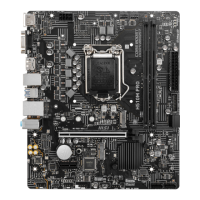
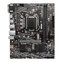
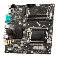
Danke, dass Sie sich für das MSI®
PRO H510TI-S01 Motherboard ent-
schieden haben. Dieses Handbuch gibt informationen über
Motherboard-Layout, Komponentenübersicht, BIOS-Setup
und Softwareinstallation.
 Loading...