Chapter 2
2-16
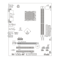
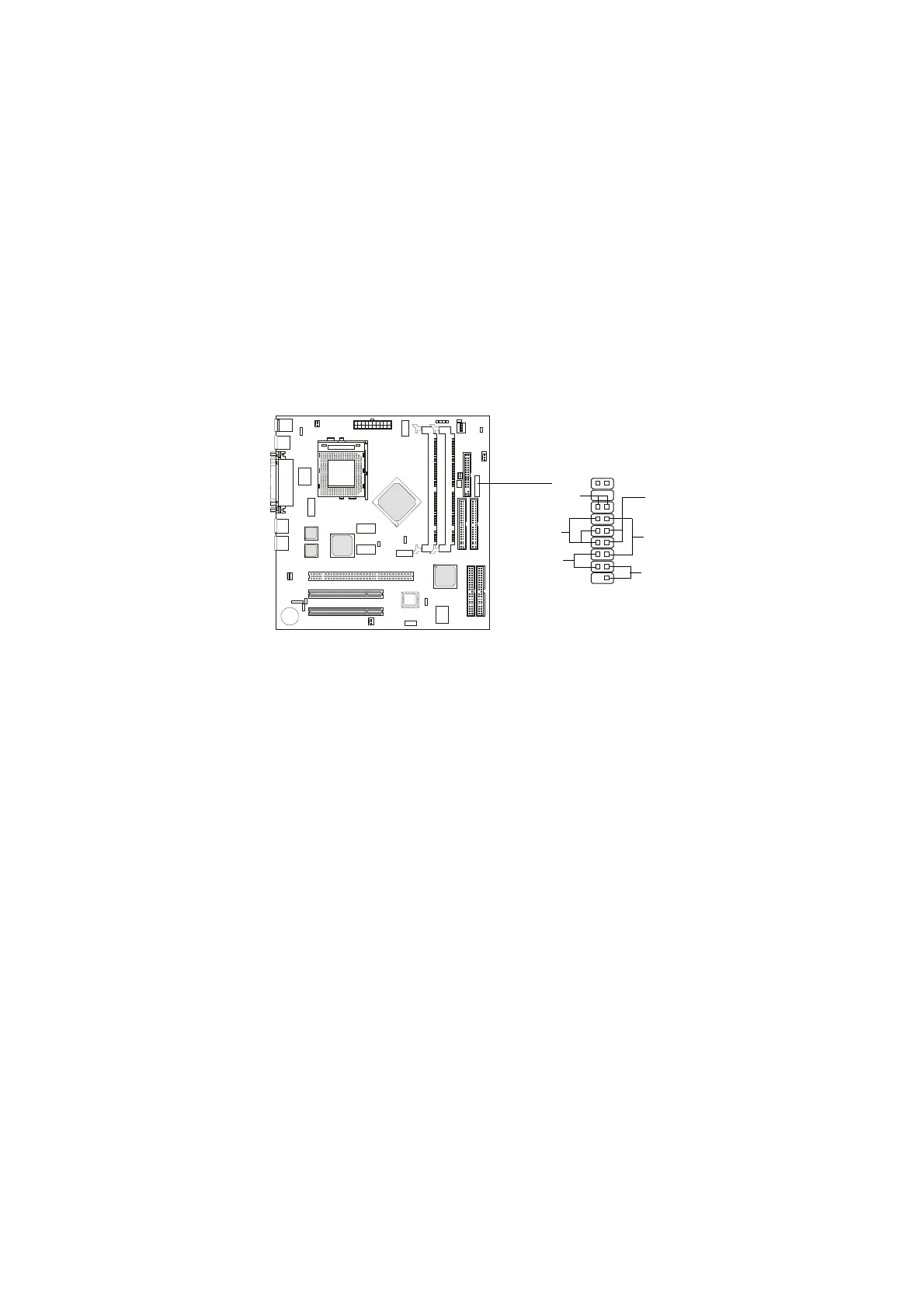
Case Connector: JFP1
The case connector block JFP1 allows you to connect to the Power Switch,
Reset Switch, Speaker, Power LED, and HDD LED on the case.
Power Switch
Connect to a 2-pin push button switch. This switch has the same feature with
JRMS1.
Reset Switch
Reset switch is used to reboot the system rather than turning the power ON/
OFF. Avoid rebooting while the HDD LED is lit. You can connect the Reset
switch from the system case to this pin.
Power LED
The Power LED is lit while the system power is on.
Speaker
Speaker from the system case is connected to this pin.
If on-board Buzzer is available:
Short pin 14-15: On-board Buzzer Enabled.
Open pin 14-15: On-board Buzzer Disabled.
HDD LED
HDD LED shows the activity of a hard disk drive. Avoid turning the power off
while the HDD led is lit. You can connect the HDD LED from the system case
to this pin.
JFP1
Power
Switch
Power
LED
Reset
Switch
HDD LED
+
Speaker
Buzzer
(short pin)
14
15
1
10