2-21
Hardware Setup
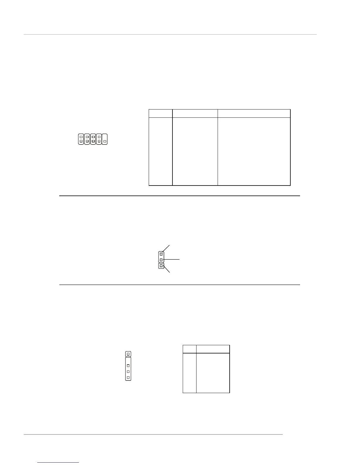
PIN SIGNAL DESCRIPTION
1 DCD Data Carry Detect
2 SIN Serial In or Receive Data
3 SOUT Serial Out or Transmit Data
4 DTR Data Terminal Ready)
5 GND Ground
6 DSR Data Set Ready
7 RTS Request To Send
8 CTS Clear To Send
9 RI Ring Indicate
Pin Definition
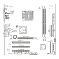
Serial Port Connector: COM2
The mainboard offers one serial port COM2. It is 16550A high speed communication
ports that sends/receives 16 bytes FIFOs. You can attach a serial mouse or other
serial device directly to it.
COM2
10
9
2
1
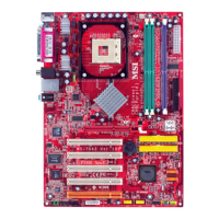
IRDA1
IrDA Infrared Module Header: IRDA1
The connector allows you to connect to IrDA Infrared module. You must config-
ure the setting through the BIOS setup to use the IR function.
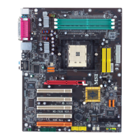
Wake On Ring Connector: WOM1
This connector allows you to connect to a modem card with Wake On Ring
function. The connector will power up the system when a signal is received through
the modem card.
WOM1
MDM_WAKEUP
5VSB
GND
1
Pin Signal
1 VCC5
2NC
3 IRRX
4 GND
5 IRTX
IRDA1 Pin Definition
1