Operating manual English
7
Operating and display
elements
`~ìíáçåK=
a~ã~ÖÉ=íç=íÜÉ=~ééäá~åÅÉ
qÜáë=Ñáêëí=ÇÉëÅêáÄÉë=íÜÉ=Åçåíêçä=~åÇ=
Çáëéä~ó=ÑìåÅíáçåëK=aç=åçí=ÉñÉÅìíÉ=
~åó=çÑ=íÜÉëÉ=ÑìåÅíáçåë=óÉí>
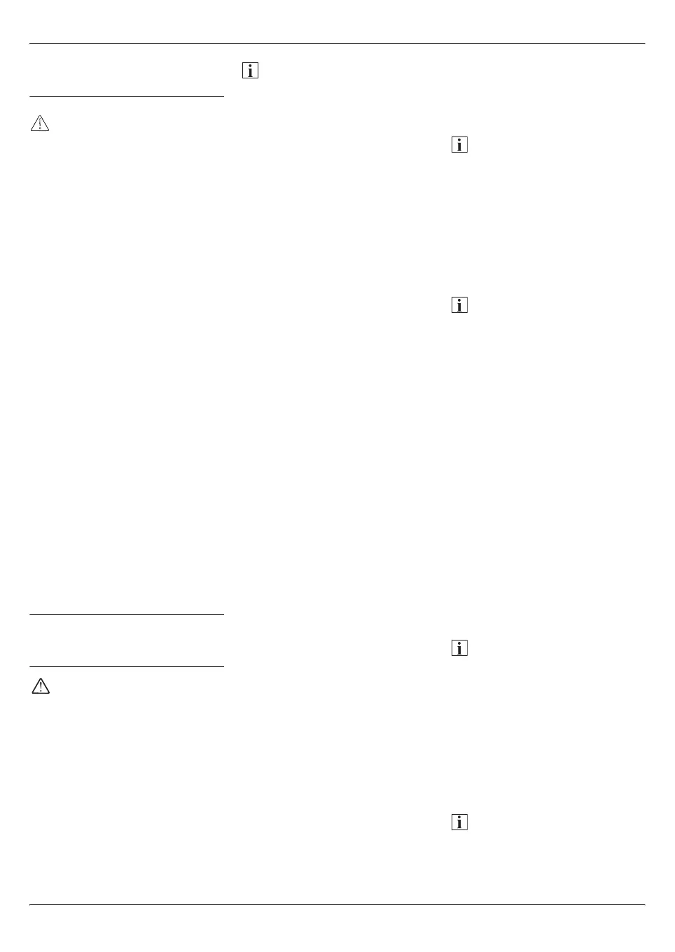
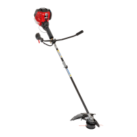
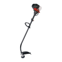
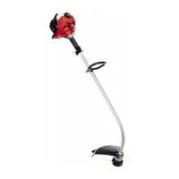
Fig. 1
1 Exhaust cover
2 Spark plug
3Starter handle
4 Tank cap
5 Intake pump/primer
6Choke lever
7 Air filter cover
8 Handle bar
9 Shaft
10 Cutting attachment cover
11 Line cutting blade
12 Line coil
13 Gearbox
14 Holder for cutting
attachment cover
15 Holder for cable harness
16 Throttle
17 Ignition switch
18 Throttle lock
19 Shoulder belt holder
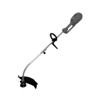
20 Cutting blade with cutting
attachment cover *
21 Retaining bar *
22 Socket wrench *
* depending on model
Installation manual
a~åÖÉê
oáëâ=çÑ=áåàìêó=Ñêçã=ÉåÖáåÉ=ÄÉáåÖ=
ëí~êíÉÇ=ìåáåíÉåíáçå~ääóK
mêçíÉÅí=óçìêëÉäÑ=Ñêçã=áåàìêóK=
_ÉÑçêÉ ïçêâáåÖ=çå=íÜÉ=ÉåÖáåÉW
Ó pïáíÅÜ=çÑÑ=íÜÉ=ÉåÖáåÉI
Ó t~áí=ìåíáä=~ää=ãçîáåÖ=é~êíë=Ü~îÉ=
ÅçãÉ=íç=ëí~åÇëíáääX=íÜÉ=ÉåÖáåÉ=
ãìëí=Ü~îÉ=ÅççäÉÇ=ÇçïåK
Ó oÉãçîÉ=ëé~êâJéäìÖ=íÉêãáå~äK
Disposal instructions
Dispose of packaging remnants,
old units, etc., in accordance with
local regulations.
Installing and setting the
handle bar
Fig. 2
Insert the handle bar (1) into the
lower holder (2).
Hook the upper retaining plate (3)
into the openings (4) of the lower
holder and secure with the toggle
screw (5).
Hold the unit in the operating
position (Fig. 13) and position the
handle bar until you have a secure
footing.
Tighten the toggle screw (5) firmly
until the handle bar (1) is secure.
Press the cable harness (6) into
the holder (7).
Adjusting the carrying
system (shoulder strap)
Fig. 3
1. Place harness over your
shoulders.
2.
Close the catch on the chest belt.
If required, readjust.
3.
Close the catch on the abdominal
belt. If required, readjust.
4. Adjust the shoulder, abdominal
and chest belts to the correct
length/width.
5. Latch the hook of the carrying
system into the holder on the unit
and adjust the attachment pad to
a comfortable length.
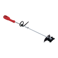
Attaching the cutting
attachment cover
Fig. 4
Attach cutting attachment cover (1)
to the holder (2) using the two
screws (3).
Tighten screws firmly.
Attaching/removing
the line head
Attaching the line head
Fig. 5
If attached, remove cutters and
blade attachment parts before-
hand. See “Removing the cutting
blade”.
Push spacer (1) onto the
drive shaft (2).
Align the 3 openings in the
spacer (3), the gearbox (4) and
the gear cover (5).
Note
If alignment is not correct, the line
head cannot be attached/removed!
Insert retaining bar (6) through the
openings (3, 4, 5) in order to secure
the gearbox.
While holding the retaining bar (6),
turn the line head (7) anti-clockwise
(to the left) onto the drive shaft.
Tighten line head firmly!
Note
Ensure that the line head (7) is
seated correctly on the spacer (1),
i.e. centred and resting flat!
Remove retaining bar from the
gear head.
Remove the line head
Fig. 6
Align the openings (3, 4, 5). Insert
retaining bar (6) through the
openings and hold in position.
Unscrew line head (7) clockwise
(to the right) off the drive shaft.
Attaching/removing the
cutting blade (depending
on model)
Attaching the cutting blade
Fig. 7
If attached, remove the line head
beforehand. See “Attaching/
removing the line head”.
Note
When attaching the cutting blade
for the first time, remove the blade
attachment parts (blade holder (8),
retaining bell (9), nut (10)) if attached.
See “Removing the cutting blade”.
Push spacer (1) onto the
drive shaft (2).
Align the 3 openings in the spacer
(3), the gearbox (4) and the gear
cover (5) (Fig. 5).
Note
If alignment is not correct, the cutting
blade cannot be attached/removed!