4.
careful not to overtighten this hardware.
With the handle in the desired position, tighten the handle-5.
crank adjustment rod at this time.
Attaching the Cables
To attach the cables, follow these steps:
Route the two cables along the handle assembly on the right-1.
hand side.
Connect the reverse cable (Red) to the reverse cable 2.
control by feeding the z-hook through the hole on the
reverse cable control from the inside towards the outside.
Refer to Fig. 3-2 on the following page.
3.
by feeding the z-hook through the hole on the clutch bail
from the outside towards the inside. See Fig. 3-2.
Note: Test the function of the reverse clutch by pulling the
reverse handle and releasing it. The handle should return
for technical assistance.
To Test the function of the forward drive bail, lift the bail
to the handle and release it. The bail should return to its
technical assistance.
To prevent personal injury or property
damage, do not start the engine until all assembly
steps are complete and you have read and
Assembly
Unpacking Instructions
NOTE: While unpacking, do not severely bend any of the control
cables.
The tiller is heavy, do not attempt to remove it from 1.
the shipping platform until instructed to do so in these
Assembly steps.
Remove all parts from the carton. Check that you have the 2.
items listed in the Contents of Carton list (contact your
local dealer or the factory if items are missing or damaged).
Remove any packaging material from the carton. Remove 3.
any staples from the bottom of the carton and remove the
carton from the shipping platform.
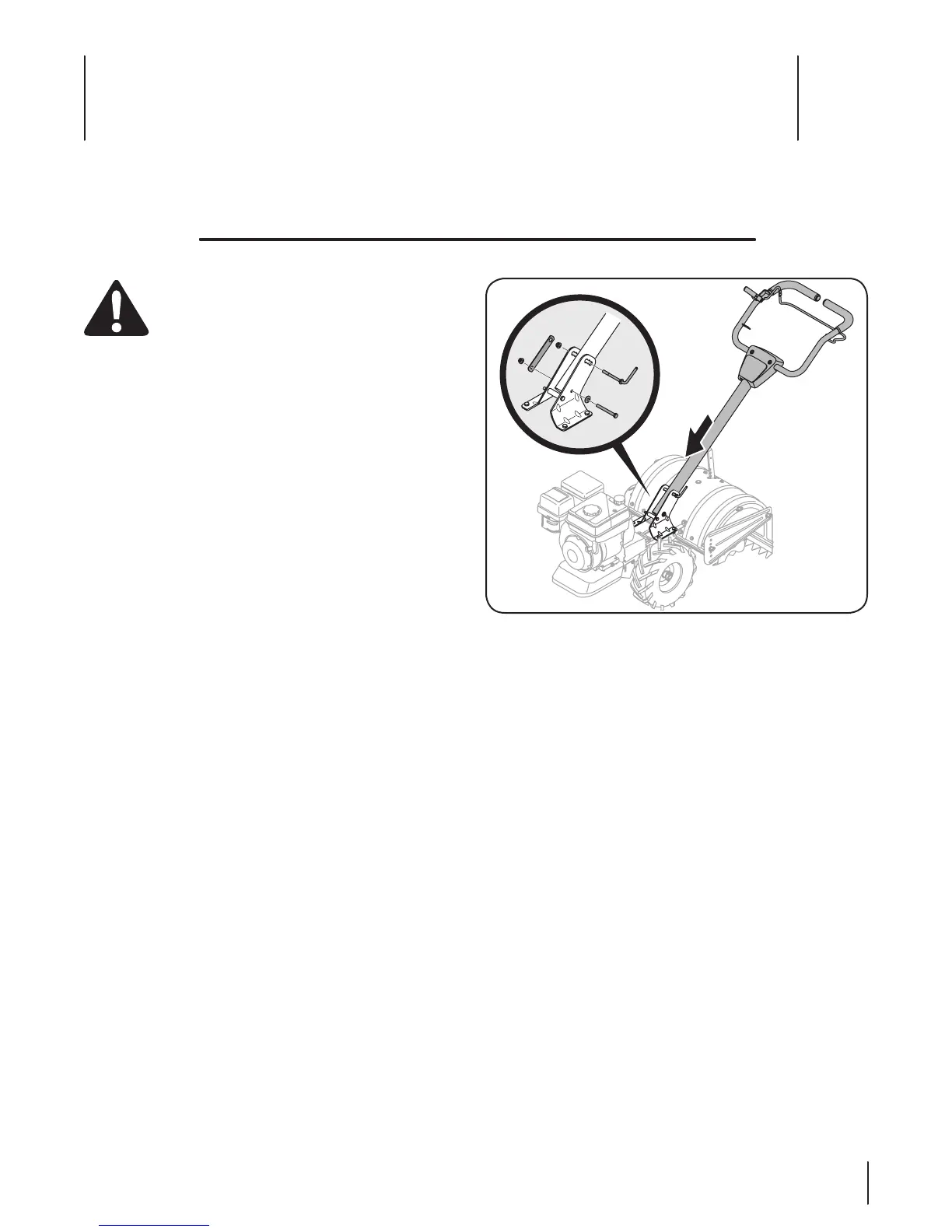
Handle
NOTE: All references to the right or left side of the tiller are from
Install the handle onto the tiller using the hardware pre-1.
installed on the handle mounting brackets. This consists of
a 5/16-18 x 3.00” hex bolt, a handle crank assembly, retainer
bracket and two 5/16-18 flange lock nuts. Remove this
hardware from the handle mounting brackets on the tiller.
Insert the handle into the handle mounting brackets, lining 2.
up the pre-drilled holes. Insert the 5/16-18 x 3.00” hex bolt
in the bottom hole from the left hand side through to the
bracket over the hex bolt and secure loosely with a bell
washer and 5/16-18 flange lock nut removed earlier.
Note: The bell washer should be positioned with the top
of the bell shape towards the hex nut which will create
tension and further secure the flange lock nut once
tightened. Do not tighten this hardware at this time.
Install the handle-crank adjustment rod into the top hole of 3.
the mounting bracket from the left hand side of the handle
assembly, secure with the other flange lock nut previously
removed. Fit the hex end of the retainer bracket over the
flange lock nut. See Fig. 3-1.
Contents of Carton
Assembly & Set-Up
3
7