MTD Engine - Series 350/450/650
18
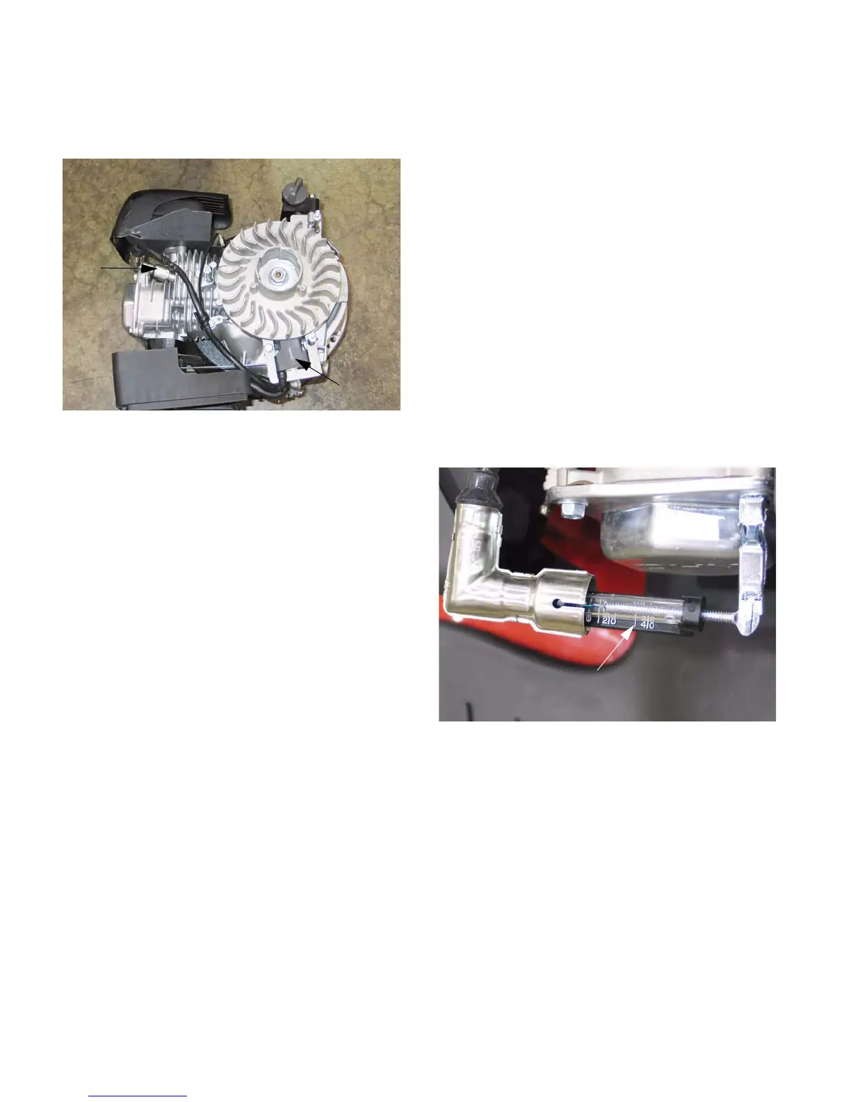
7.8. The ignition module for the Series 650 engines
is mounted off-set from the cylinder.
See Figure 7.8.
7.9. The ignition modules differ between the two
basic engine designs, because of the longer dis-
tance from the module to the plug on the Series
650 engines. The high tension lead from the
module to the spark plug is longer on these
engines than on the smaller ones.
7.10. The flywheels are interchangeable between the
two engine designs. Even though the module is
mounted in different locations, the relationship
between the key-way and the magnets is the
same. The keyways in the crankshafts are
indexed differently to suit the module location.
7.11. On installation, confirm that the key is properly
seated in the key-way, and that the tapers are
fully seated. Key or keyway failure may result
from improper seating.
7.12. Install the flywheel nut to a torque of 41-48 ft-lbs.
(55-65 Nm).
7.13. Use a 10mm wrench to remove the ignition mod-
ule or adjust the air gap between the module and
the flywheel.
• The air gap should be .016”-.024” (.4-.6mm).
• The module is attached with the high-tension
lead facing up.
• One leg of the module is secured by a stud that
also supports the fan shroud, the second leg is
secured by a screw.
• On Series 350 and Series 450 engines, there is
a spacer between the cylinder and the module at
both mounting points.
• On the Series 650 engines, there is a spacer
between the module and the crankcase on the
stud only.
• On module installation, set the air gap, tighten
the stud and screw to a torque of 84 in-lb (10
Nm), then re-check the air gap.
7.14. Diagnosis: refer to steps 5.53 through 5.62 of
the MAINTENENACE AND ADJUSTMENT
INFORMATION section of this manual to isolate
the ignition coil from the stop switch.
7.15. Normal performance of the coil is to produce at
least 10,000 volts at starter-rope pull-through
speed. See Figure 7.15.
7.16. Presence or absence of strong spark, with the
stop switch and wire known to be good, is gener-
ally enough to identify the ignition coil as good or
bad. Resistance readings may help confirm the
source of the failure, but are generally unneces-
sary.
7.17. It is possible for the transistorized portion of the
module to fail, yet resistance tests will show the
windings to be good. A simple spark-gap tester
is will give an adequate indication of the ignition
system’s condition.
Figure 7.8
Module
Series 650 engine: note module location
and length of high tension lead
Spark
plug
Figure 7.15
Inexpensive spark gap tester
provides usable information
www.mymowerparts.com
For Discount White Outdoor Parts Call 606-678-9623 or 606-561-4983
 Loading...