MTD Engine - Series 350/450/650
17
7. IGNITION SYSTEM
7.1. The ignition system is a transistorized magneto,
contained in a single module.
• The magneto is a three leg design.
• The magneto is energized by the passing of a
pair of magnets mounted in the flywheel.
• Ignition timing is set by the location of the fly-
wheel in relation to the crankshaft. Proper timing
is maintained by a steel key.
7.2. Remove the recoil assembly as described in the
STARTER SERVICE section of this manual.
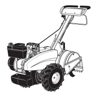
7.3. Lift the fan shroud off of the three studs that
locate it. See Figure 7.3.
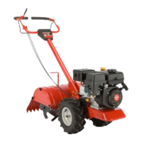
7.4. To remove the flywheel, remove the flywheel nut
using a 19mm wrench. See Figure 7.4.
Figure 7.3
Fan shroud
Shoulder
bushings
Shoulder
bushings fit
over studs
Figure 7.4
7.5. Hold the safety bail down using a spring clamp,
and remove the flywheel using an appropriate
puller.
CAUTION: If the flywheel shows any signs of
physical damage such as cracks, broken vanes,
or damaged key-way, replace it. A damaged fly-
wheel poses a threat of burst failure. Burst fail-
ures are extremely hazardous to surrounding
people and property.
7.6. Inspect the key, keyway, and tapered mating sur-
faces of the flywheel and crankshaft.
See Figure 7.6.
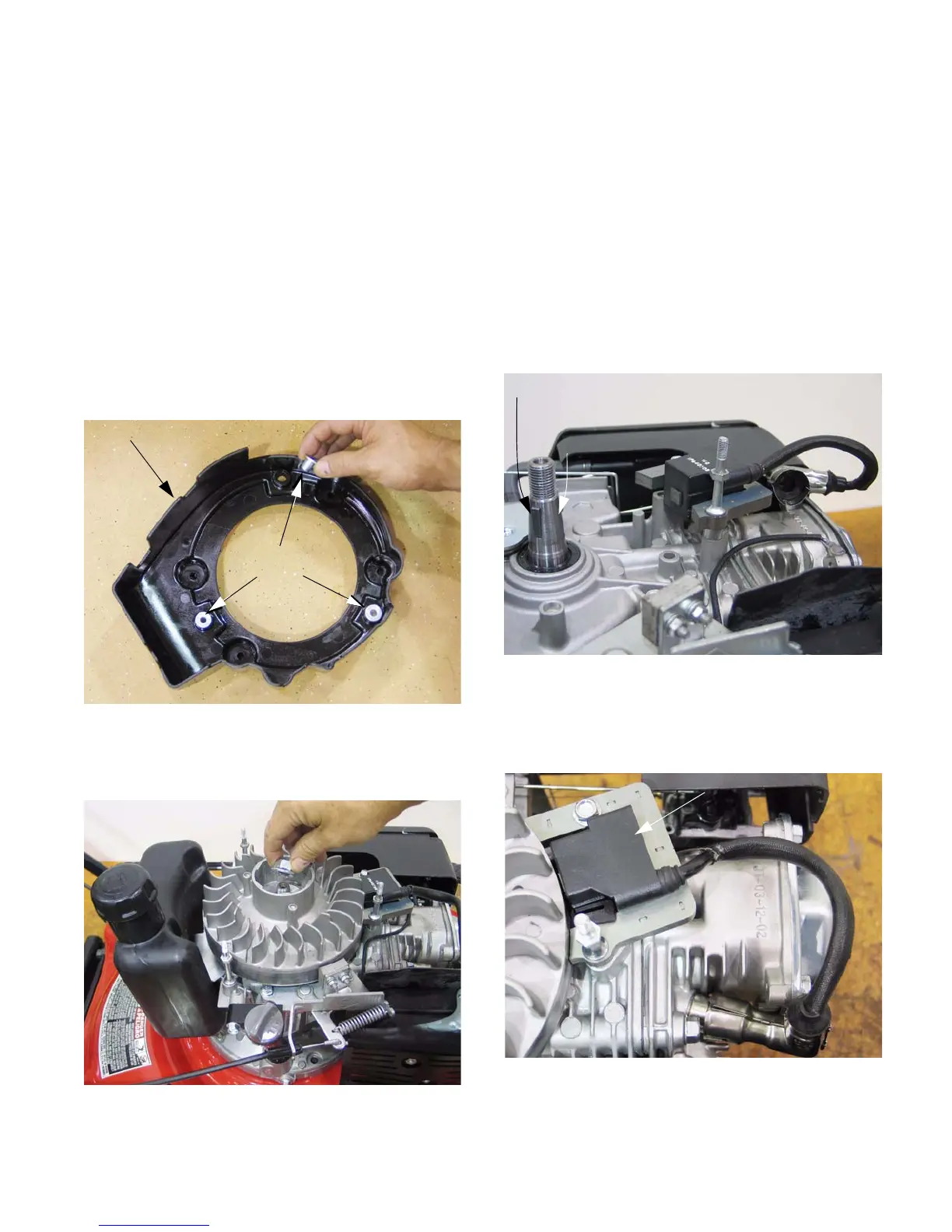
7.7. The ignition module for the Series 350 and
Series 450 engines is mounted to the cylinder.
See Figure 7.7.
Figure 7.6
Key
Taper
Figure 7.7
Module
www.mymowerparts.com
For Discount White Outdoor Parts Call 606-678-9623 or 606-561-4983
 Loading...