MTD Engine - Series 350/450/650
32
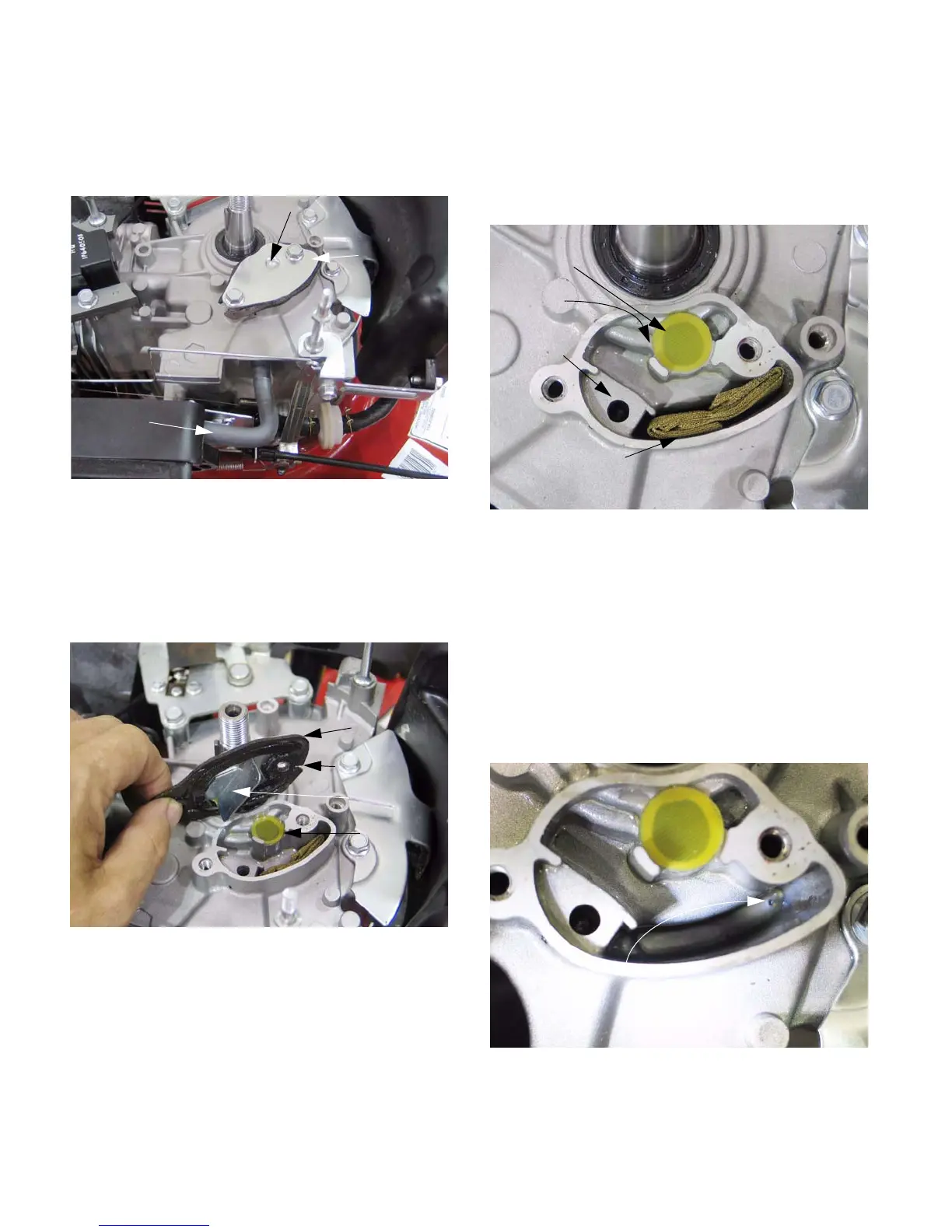
11.6. The PCV chamber is accessible by removing the
flywheel, as described in steps 7.2 through 7.6
of the IGNITION SYSTEM section of this man-
ual. See Figure 11.6.
11.7. Remove the two screws that hold the PCV
chamber cover to the engine block using a
10mm wrench.
11.8. The cover and gasket can be separated from the
chamber. See Figure 11.8.
NOTE: The dimple in the cover helps locate the
fiber disc over the port that leads into the crank-
case.
NOTE: the baffle in the cover helps separate the
oil from the air in the chamber. It is desirable to
allow the air out, but important to keep as much
oil as possible in the engine.
11.9. The disc acts as a check valve: pressure pulses
force it off of the port, but it falls back over the
port when the pressure drops.
11.10. The folded wire mesh in the chamber also helps
separate the oil from the air. See Figure 11.10.
11.11. The port to the PCV hose is near the top of the
chamber. The oil tends to settle out of suspen-
sion, leaving mostly air to exit the chamber
through the PCV hose.
11.12. The screen accumulates droplets of oil, which
eventually drip down to the bottom of the cham-
ber. Beneath the screen is a drain-back port,
leading to the crankcase. the size of the port is
small enough that significant pressure does not
flow through it. See Figure 11.12.
Figure 11.6
PCV tube
PCV
chamber
cover
Dimple
Figure 11.8
Cover
Gasket
Baffle
Disc
Figure 11.10
Disc
Port to
Folded wire mesh
crankcase
PCV hose
Port to
Figure 11.12
Drain-back port
www.mymowerparts.com
For Discount White Outdoor Parts Call 606-678-9623 or 606-561-4983
 Loading...