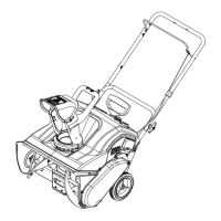
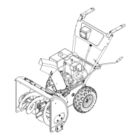
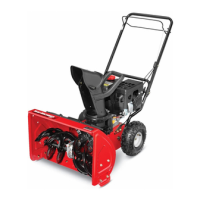
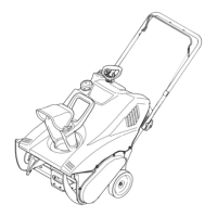
15Section 3 — controlS & operation
Snow thrower controls and features are
described below and illustrated in Figure 3-1.
NOTE: This Operator’s Manual covers several
models. Snow thrower features may vary by
model. Not all features in this manual are
applicable to all snow thrower models and the
snow thrower depicted may differ from yours.
NOTE: All references to the left or right side
of the snow thrower are from the operator’s
position. Any exceptions will be noted.
Engine
Refer to the Engine Operator’s Manual for
details regarding all engine-related controls and
features.
Shift Lever (6-Speed Transmission)
(If equipped)
The shift lever is located on the handle panel and
is used to determine ground speed and direction
of travel.
Forward
There are six forward (F) speeds. Position
one (1) is the slowest and position six (6) is the
fastest.
Reverse
There are two reverse (R) speeds. Position one (1)
is the slower and position two (2) is the faster.
Shift Lever (Hydro Transmission)
(If equipped)
The shift lever is located on the handle panel and
is used to determine ground speed and direction
of travel. The further forward the lever is the
faster the unit will travel. Moving past the detent
position to the reverse direction will move the
unit in reverse.
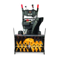
Chute Assembly
Snow drawn into the auger housing is
discharged out the chute assembly.
Skid Shoes
Position skid shoes based on surface conditions.
Adjust upward for hard-packed snow. Adjust
downward when operating on gravel or crushed
rock surfaces. See Skid Shoe Adjustment section
on page 13.
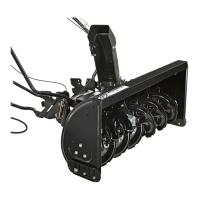
Augers
When engaged, the augers rotate and draw
snow into the auger housing.
Headlight(s) (If Equipped)
The headlight is located on the handle panel and
is automatically turned ON when the engine is
started.
LED Light Bar (If Equipped)
The LED headlight is located on top of the auger
housing and is automatically turned ON when
the engine is started.
Drift Cutters (If Equipped)
The drift cutters are designed for use in deep
snow. Their use is optional for normal snow
conditions. Maneuver unit so that the cutters
penetrate a high standing snow drift to assist
snow falling into the augers for throwing.
Heated Grips (If Equipped)
Caution: It is recommended that
you wear gloves when using the
heated grip. If the heated grips
become too hot, turn it OFF.
To activate the heated grips, move switch found
on top (a) of or on the rear (b) of dash panel into
the ON position. See Figure 3-2. To turn OFF
heated grips, move switch to the OFF position.
Switch ON Switch OFF
(b)
(a)
(b)
(a)
Switch ON
Switch OFF
Figure 3-2
Auger Control Lever
The auger control lever is located on the left
handle. Squeeze the control lever against the
handle to engage the augers and start snow
throwing action. Release to stop.
See Figure 3-3.
Figure 3-3
IMPORTANT: Refer to the Auger Control Test
information on page 13 prior to operating your
snow thrower. Read and follow all instructions
carefully and perform all adjustments to verify
your snow thrower is operating safely and
properly.
Drive Control Lever / Auger Clutch Lock*
The drive control lever is located on the right
handle. Squeeze the control lever against the
handle to engage the wheel drive. Release to
stop. See Figure 3-4.
Figure 3-4
*On select models, the drive control lever also
locks the auger control lever so that you can
operate the chute directional control without
interrupting the snow throwing process. If the
auger control lever is engaged simultaneously
with the drive control lever, the operator can
release the auger control lever (on the left
handle) and the augers will remain engaged.
Release both control levers to stop augers and
wheel drive.
NOTE: Always release drive control lever before
changing speeds on all units except hydrostatic
models. Failure to do so will result in increased
wear on your machine’s drive system.
Steering Trigger Controls
(If Equipped)
The left and right wheel steering trigger controls
are located on the underside of the handles.
Refer to Figure 3-5.
IMPORTANT: Units with Hydro Transmission
- When moving the unit without starting the
engine, squeeze both right and left triggers to
disengage the drive.
Figure 3-5
• Squeeze the right trigger control to turn
right.
• Squeeze the left trigger control to turn
left.
CAUTION: Operate the snow
thrower in open areas until you are
familiar with these controls.
 Loading...