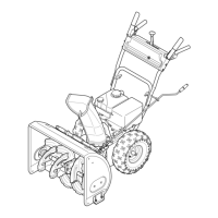
10 Section 2 — ASSembly & Set-Up
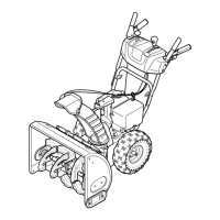
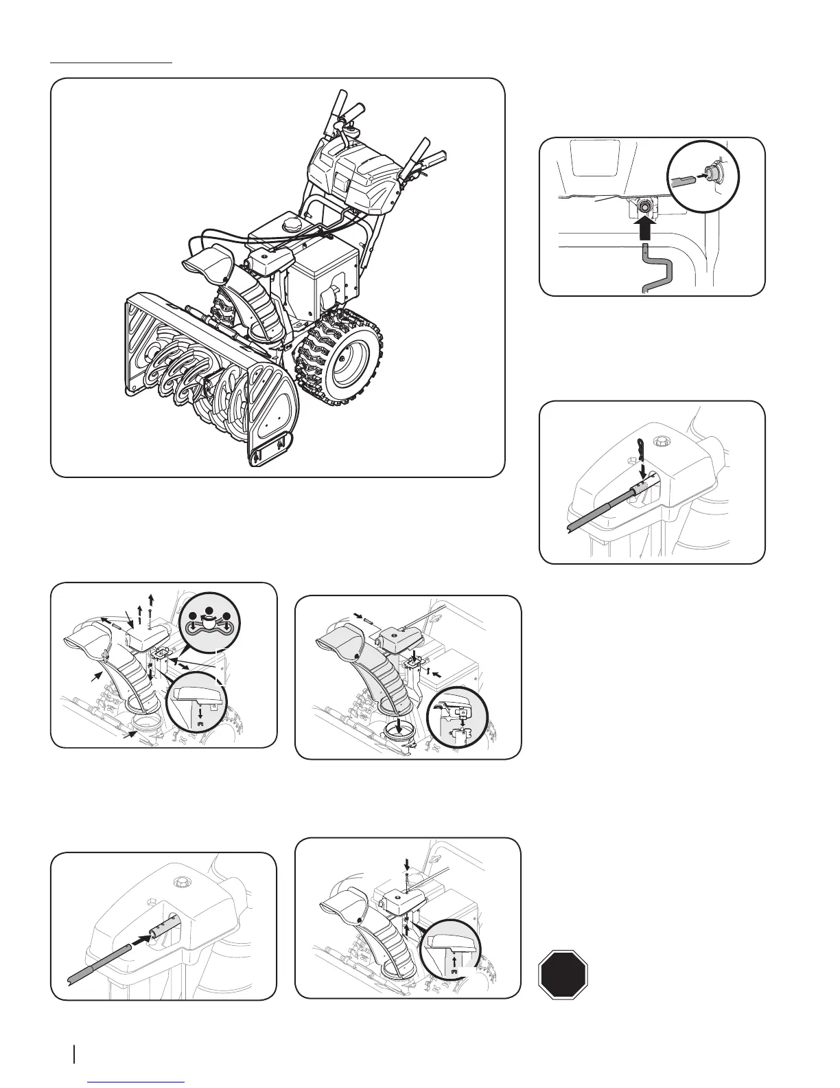
1. Remove cotter pin (a), wing nut (b) and
hex screw (c) from chute control assembly.
Remove clevis pin (d) and bow-tie cotter
pin (e) from chute support bracket.
See Figure 2-23.
(c)
(e)
1
1
2
Chute
Chute
Support
Bracket
Chute Base
(a)
(d)
(b)
Chute Control
Assembly
Figure 2-23
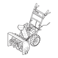
2. Insert round end of chute control rod into
chute control assembly. Push rod as far
into chute control assembly as possible,
keeping holes in rod pointing upward. See
Figure 2-24.
Figure 2-24
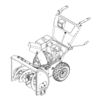
3. Place chute onto chute base and ensure
chute control rod is positioned under
handle panel. Secure chute control
assembly to chute support bracket with
clevis pin (d) and bow-tie cotter pin (e)
removed in Step 1. See Figure 2-25.
Figure 2-25
4. Finish securing chute control assembly by
installing hex screw (c) and wing nut (b)
removed in Step 1. See Figure 2-26.
Figure 2-26
5. Insert other end of chute control rod into
coupler below handle panel. Make sure
to line up flat end of rod and flat end
of coupler. You may need to rotate rod
around until these two surfaces line up.
See Figure 2-27 inset.
Figure 2-27
6. Push chute control rod toward the control
panel until hole in rod lines up with
middle hole in chute control input and
insert cotter pin (a) removed in
Step 1. See Figure 2-28.
Figure 2-28
NOTE: There is a reference hole provided
at rear end of control rod to help know
when holes are vertical.
NOTE: Hole furthest from chute control
assembly is used to achieve further
engagement of chute control rod into
coupler if required. Refer to Service
section for Chute Control Rod adjustment
on page 20.
Hole closest to chute control assembly
is used for manual movement of chute
assembly if required. Refer to Controls &
Operation section on page 16.
7. It is important that all cables be routed
properly. Refer to “Chute Control Cable
Routing” page on 7.
NOTE: On units equipped with a cable
tie securing the cables to the rear of the
gas tank, pull the cables towards the chute
and pull the cable tie snug to secure the
cables in place.
NOTE: For smoothest operation, cables
should all be to left of chute directional
control rod.
STOP
STOP! Continue to Adjustments -
(page 13).
Electric Chute Control
Figure 2-22
 Loading...