11Section 2 — ASSembly & Set-Up
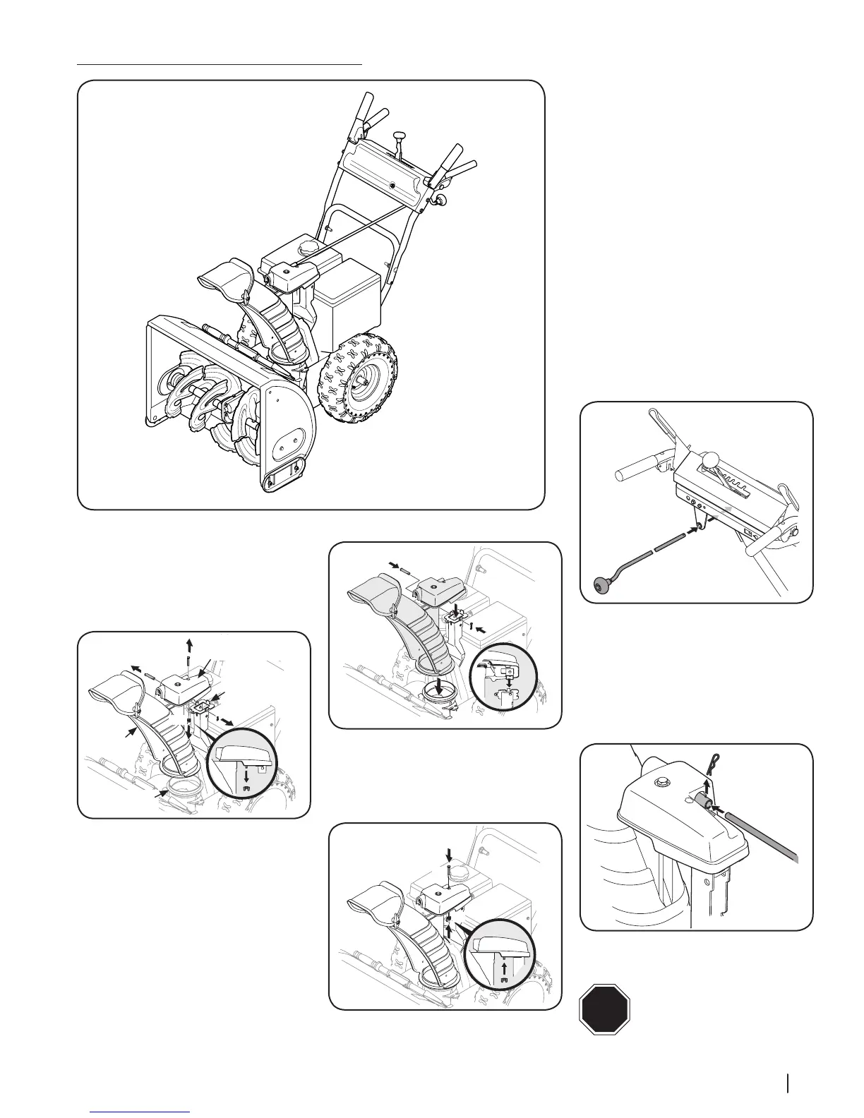
1. Remove wing nut (a) and hex
screw (b) from chute control assembly and
clevis pin (c) and cotter pin (d) from chute
support bracket. Position chute assembly
(forward-facing) over chute base. See
Figure 2-30.
(a)
(b)
(c)
(d)
Chute Control
Assembly
Chute
Chute
Support
Bracket
Chute
Base
Figure 2-30
2. Place chute assembly onto chute base and
secure chute control assembly to chute
support bracket with clevis pin (c) and
cotter pin (d) removed in Step 1.
See Figure 2-31.
Figure 2-31
3. Finish securing chute control assembly to
chute support bracket with wing
nut (a) and hex screw (b) removed in Step
1. See Figure 2-32.
Figure 2-32
4. Guide the chute crank rod through the
bracket located on the rear of the handle
panel . See Figure 2-33.
Figure 2-33
5. Remove the cotter pin (a) and insert the
chute crank rod (b) into the connector on
the chute control assembly.See Figure
2-34.
6. Align the hole in the chute crank rod with
the hole in the connector, secure with
cotter pin (a) previously removed.
Figure 2-34
STOP
STOP! Continue to Adjustments -
(page 13).
Overhead Chute Control (with Chute Control Rod)
Figure 2-29
(a)
(b)
(c)
(d)
 Loading...