61, 65 and 70 Series Vertical Shaft Engines
120
10. Install the sump by:
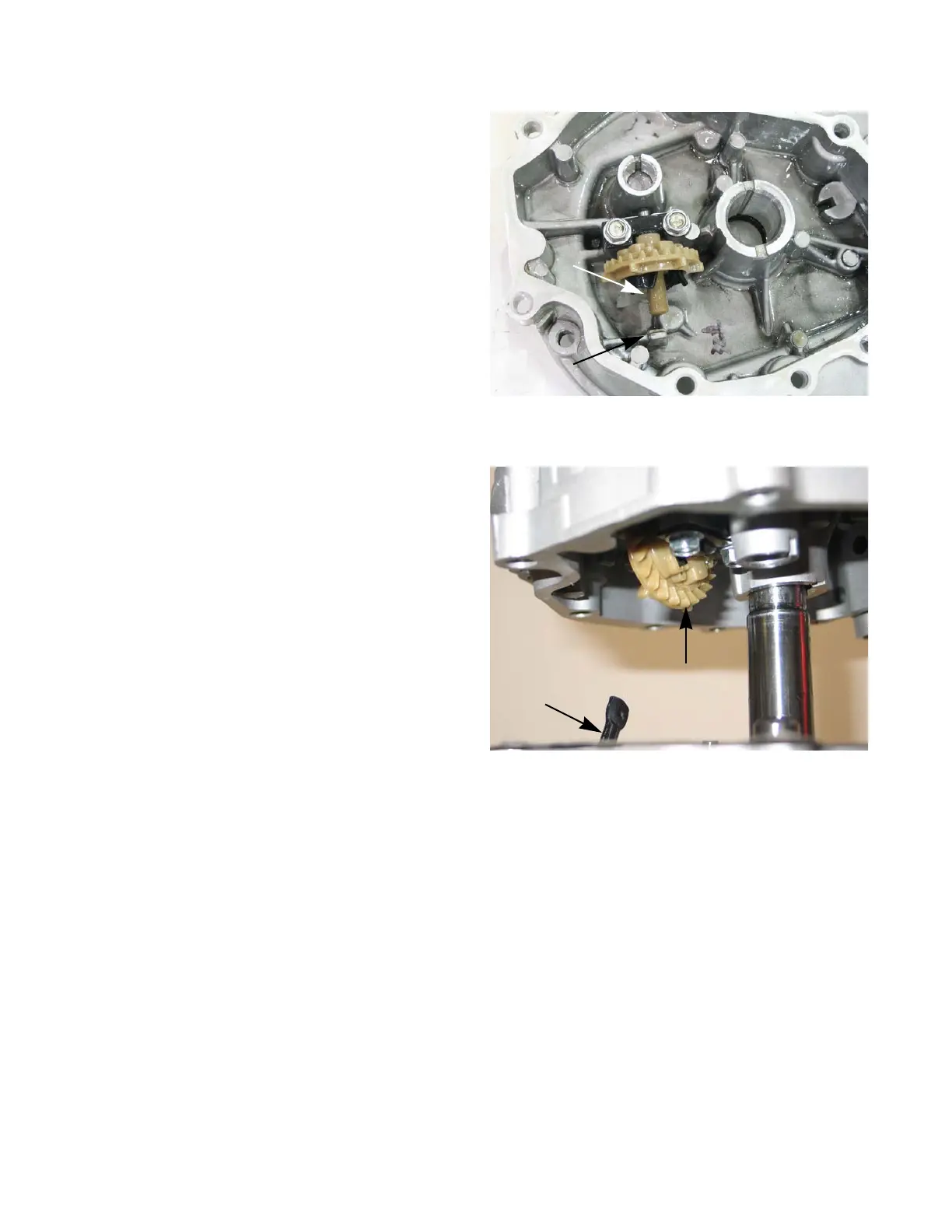
10a. If removed, install the governor gear and cup
by following the steps described in Chapter 4:
Fuel system and Governor.
10b. Place a new gasket on the sump, let the align-
ment dowels hold it in place.
10c. Rotate the governor arm so that it is pointing
straight up.
10d. Using a seal protector, slide the sump on to
the crank shaft.
NOTE: The governor arm must slide between the
governor cup and the governor arm stop.
See Figure 10.31.
NOTE: Watch the governor arm as the sump is slid
into place. Rotate the arm as needed to
allow the arm to slip into place. See Figure
10.32.
10e. Rock sump until it seats fully against the cylin-
der block.
10f. Install the sump bolts and tighten to a torque of
89 in-lbs (10 Nm).
NOTE: Use a star torque pattern to tighten the
sump bolts.
11. Install the cylinder head by following the steps
described in Chapter 9: Cylinder head.
12. Install the muffler by following the steps described in
Chapter 8: Exhaust.
13. Install the fuel tank by following the steps described in Chapter 4: Fuel systems and Governor.
14. Install the carburetor by following the steps described in Chapter 3: Air Intake and Filters.
15. Install the flywheel and module by following the steps described in Chapter 7: Ignition system.
NOTE: If equipped, install the engine brake by following the steps described in the application’s service man-
ual.
16. Install the blower housing and starter by following the steps described in Chapter 6: Starter.
17. Install the engine on the application by following the steps described in the application’s service manual.
18. Install the spark plug by following the steps described in Chapter 7: Ignition system.
19. Fill the engine with oil and fuel by following the steps described in Chapter 1: Introduction.
20. Test run the engine in a safe area and make any carburetor and governor adjustments needed.
Figure 10.31
Governor
cup
Governor arm stop
Figure 10.32
Governor arm
Governor
gear

 Loading...


