FUEL SYSTEM AND GOVERNOR
63
7. Slide the governor shaft into the engine block from
the inside of the engine.
8. Carefully slide a new seal over the governor shaft
and seat using a 1/4” deep well socket. See Figure
4.63.
9. Install the hair pin clip.
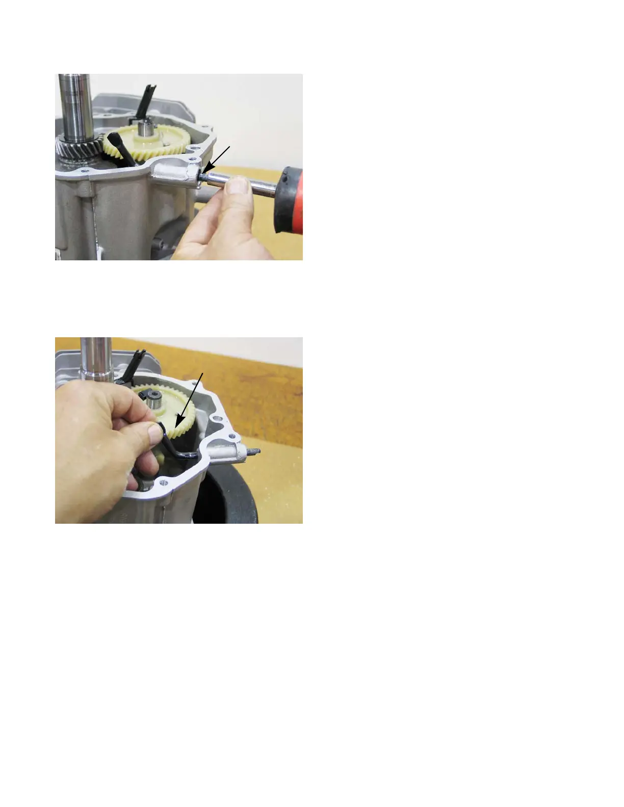
10. Rotate the governor shaft so that the bent end is
standing straight up. See Figure 4.64.
NOTE: If the governor shaft is not pointing up while sliding
the sump on, the governor shaft will not catch the
governor cup. This will prevent the governor from
changing the engine rpm and usually presents as
an over-speeding engine.
11. Install the sump by following the steps described in
Chapter 10: Disassembly.
12. Rotate the governor shaft clockwise as far as it will
go.
13. Position the top of the arm about 3/16” (.476cm) from
the boss on the casting that provides a mounting
point for the fuel tank bracket.
14. Install the governor arm by following the steps
described in the previous section.
15. Install the engine on the unit.
16. Test run the engine and adjust the top no load engine
RPMs by following the steps described in “Disassem-
bly and rebuilding the carburetor” section of this
chapter.
Figure 4.64
Governor shaft must point
straight up while sliding
the sump on

 Loading...