CRANKSHAFT, PISTON AND CONNECTING ROD
71
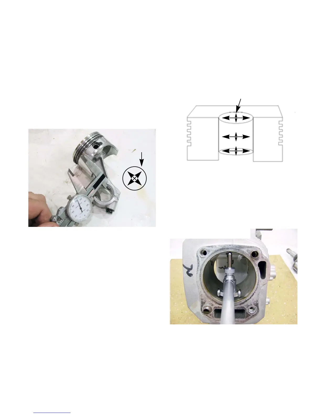
Connecting rod inspection
1. Inspect the connecting rod for cracks or any
signs of damage.
2. Install the rod cap and tighten to a torque of 106
-124 in-lbs (12 - 14Nm).
3. Measure the inside diameter of the connecting
rod and compare the measurements to those
listed in the chart at the end of this chapter.
See
Figure 10.12.
NOTE: Take two measurements 90 degrees
apart. This will check the out of roundness of the
connecting rod.
NOTE: Connecting rods are not available as ser-
vice parts. If the connecting rod is bad, the
engine must be short blocked.
4. Take the crank shaft journal measurement and
subtract it from the connecting rod measurement
to get the connecting rod to journal running
clearance. Compare that number to the one
listed in the chart at the end of this chapter.
NOTE: Plasti-gauge can be used to measure the
connecting rod to journal running clearance, but
it is very technique sensitive and it is not as reli
-
able as the method described above.
Figure 10.12
Measure at
right angles
Cylinder inspection
1. Clean and inspect the cylinder, inside and out.
NOTE: If there is any sign of damage, especially
cracked cooling fins, short block the engine.
NOTE: Take two measurements of the cylinder
bore 90 degrees apart at the top, bottom and
middle of the cylinder.
See Figure 10.13.
NOTE: The measurements can be made using
telescoping gauges, inside micrometers or dial
indicating bore gauge.
See Figure 10.14.
Figure 10.13
Measure the cylinder bore
Figure 10.14
Measuring the cylinder bore using
a dial indicating bore gauge
www.mymowerparts.com
For Discount White Outdoor Parts Call 606-678-9623 or 606-561-4983