6
SECTION 2: ASSEMBLING YOUR SNOW THROWER
Unpacking
• Remove staples or break glue on the top flaps of
the carton. Remove any loose parts included with
unit (i.e., Operator’s Manual, etc).
• Cut along corners and lay end of carton down flat.
Remove packing material.
• Roll unit out of carton. Check carton thoroughly for
loose parts before discarding.
Loose Parts
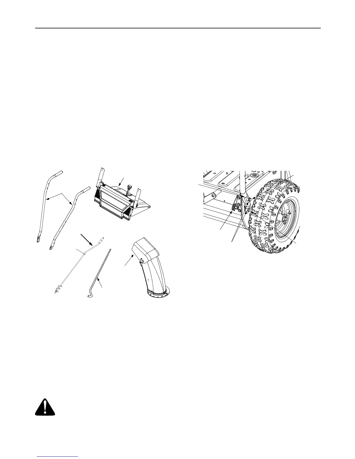
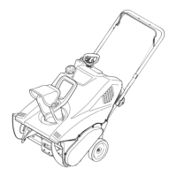
Figure 1 shows parts of the snow thrower packed
loose in the carton. You will need these parts along
with hardware from the hardware pack, illustrated on
the next page, to assemble the equipment. Identify the
loose parts before proceeding to assemble.
Figure 1
1. Right and Left Handles
2. Handle Panel Assembly
3. Chute Assembly
4. Chute Directional Control Assembly
5. Shift Rod
6. Hardware Pack
Tools Required For Assembly
1. Pair of pliers
2. Two adjustable wrenches
WARNING: Disconnect spark plug wire
and ground it against the engine to prevent
unintended starting.
NOTE: All references to right or left side of the snow
thrower are determined from behind the unit in the
operating position.
Assembly Tips: For convenience in assembly,
remove the chute from the carton and lay it on top of
the engine. Do not unwrap the chute till you have
installed the handle panel and the clutch cables.
Attaching Handle
(Hardware A)
• Place right handle in position against the snow
thrower so the flat side of the handle is against the
snow thrower. Secure bottom hole in handle to
snow thrower using 3/4” hex bolt and lock washer.
Do not tighten at this time. See Figure 2.
Figure 2
• Place handle tab over the upper hole on the
handle so the curve in the handle tab matches the
curve of the handle. See Figure 2. Secure to the
snow thrower using1-3/4” hex bolt and lock
washer; do not tighten at this time. Repeat on the
other side. Do not tighten at this time.
• Place the handle panel in position between the
two handles. To hold the handle panel in place,
depress both controls against the handles. While
continuing to hold the right control, release the left
control (the auger control lock will keep left control
engaged). See Figure 3.
• Fasten right side of the handle panel by inserting
two carriage bolts through handle and handle
panel (bolts must go through both the plastic and
metal parts of the handle panel). See Figure 3.
Secure with cupped washers (cupped side against
handle panel) and lock nuts.
• Repeat on the other side.
• Tighten the four hex bolts used earlier to attach
bottom of the handles to the snow thrower frame.
See Figure 2.
Handle Panel
Handles
Chute Directional
Control
Shift
Discharge
Rod
Chute
Cable Roller
Guide
Handle
Tab
Lock
Washers
1 3/4” Hex
Bolt
3/4” Hex
Bolt