10
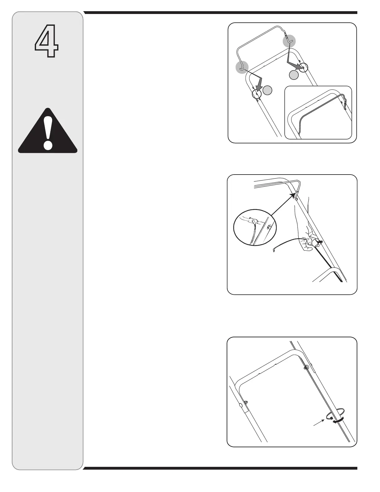
Attaching the Blade Control Handle
NOTE: If the blade control handle got displaced either
during shipping or during assembly of other two handles,
reassemble it now. If the blade control handle is firmly
secured in place, you may proceed to the next assembly.
• Toreattachthebladecontrolhandletotheupper
handle, first identify the proper holes in the upper
handle. This can be done by placing the blade control
handle flat against the upper handle. The ends of
the blade control handle will approximate the hole
positions.
• Insertthecurvedendofthebladecontrolhandleinto
the right hole. See Figure 4-5.
• Squeezethehandlein,andinsertthestraightendof
the blade control handle into the left hole of the upper
handle.
• Squeezethebladecontrolhandleagainsttheupper
handle to check for proper assembly.
NOTE: The hole in the blade control handle must be on
the left side and the control handle must touch the upper
handle when squeezed.
Attaching Blade-Brake Cable
• Makecertainthebladecontrolhandleisonthetopof
the upper handle.
• Thebrakecableisattachedtotheengine,andhas
a “Z” fitting on the loose end. Route the brake cable
under the lower handle. Snap the plastic fitting into
the hole on the inside of the upper handle as shown
in Figure 4-6.
• Hookthe“Z”endofthebrakecableintotheholein
the blade control handle from the outside to the inside
as shown in Figure 4-6, inset.
• Brakecablemustbeassembledasshownforproper
blade brake operation.
• Thecablemustberoutedproperlytoavoidcontact
with all sharp edges and hot surfaces. Such contacts
damage the cable and render the controls inopera-
tive.
Securing Brake Cable
(Hardware F)
• Securethecabletothelowerlefthandlenearthe
base of the unit with a cable tie from the hardware
pack. Trim off extra length of the cable tie. See Figure
4-7.
Figure 4-5
Figure 4-6
4
WARNING
The cable must be
routed properly to
avoid contact with
all sharp edges and
hot surfaces. Such
contacts damage the
cable and render the
controls inoperative.
IMPORTANT
The blade control
handle is a safety
device. Never at-
tempt to bypass its
operations.
Setup and
Adjustments
Figure 4-7
 Loading...