318 Load Unit Installation
55
Prerequisite You must have either a cable assembly drawing of your test system, or you must
know the system controller well enough to determine each type of cable
connection.
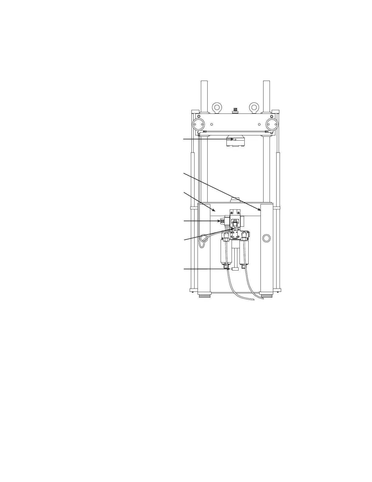
1. The force transducer is connected to a DC conditioner in the controller.
2. The ground connection is located on the back of the control panel. This is
usually connected to a chassis ground on a console or the controller chassis.
3. The load unit control panel is connected to the controller. It contains the
emergency stop and crosshead lock signals.
4. The servovalve is connected to a valve driver in the controller.
5. The actuator manifold is connected to the hydraulic service manifold (HSM)
connector on the controller. The actuator manifold may include a
proportional valve or solenoid valves. Controllers can have two connectors
(one for each HSM type) or one connection that may be configured. See
your controller documentation.
6. The displacement sensor (also called an linear variable displacement
transducer or LVDT) is connected to an AC conditioner in the controller.
 Loading...