Maintenance
MTS Landmark™ Tabletop Load Units - Product Information 105
Compute the TIR. Take the maximum dial indicator reading and subtract the
minimum dial indicator reading.
Load Unit Rating TIR
25 kN (5.5 kip) or less > 0.038 mm (0.0015 in)
C. If the TIR is 0.038 mm (0.0015 in) or less, the force transducer is accurately aligned
with the actuator. This completes the procedure.
If the TIR is greater than 0.038 mm (0.0015 in), the force transducer needs to be
aligned with the actuator. Continue to the next step.
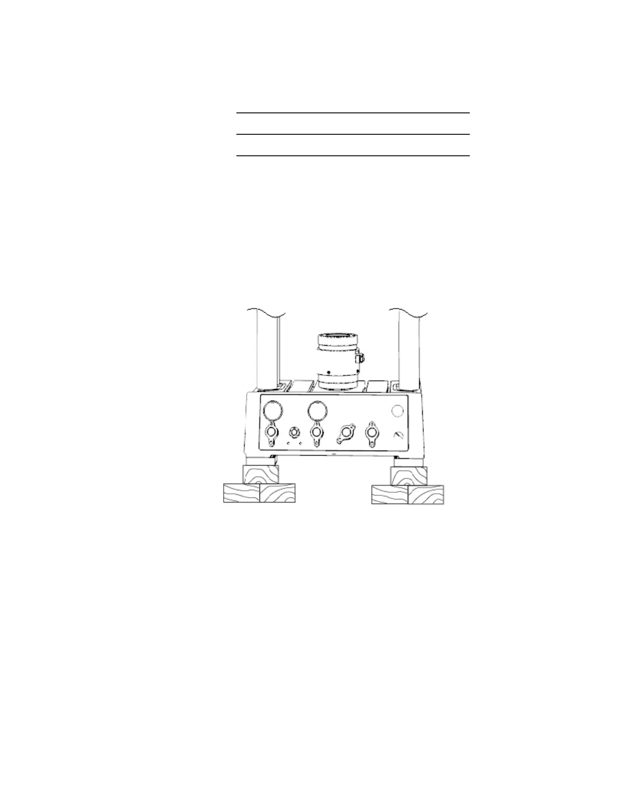
4. Raise the load unit.
The load unit must be raised above the mounting surface to access the threaded fasteners of
the force transducer. The threaded fasteners are accessed from the bottom of the load unit.
A. Loosen the load unit’s legs from their mounting surface.
B. Put blocks of wood under the load unit’s legs to increase the clearance between the
load unit and its mounting surface.
C. The load must be raised high enough to use a torque wrench on the force
transducer’s threaded fasteners.
5. Adjust the force transducer alignment.
A. Loosen the force transducer just enough so that it will move when tapped by a nylon
mallet.
l Loosen the threaded fastener that holds the axial force transducer.
l Loosen the eight threaded fasteners that hold the axial-torsional force
transducer.