Maintenance
120 MTS Landmark™ Tabletop Load Units - Product Information
reduced to a minimum, and then proceed to Step 4. If the adjustor pin still does not
turn, proceed to the next step.
D. Ensure that system hydraulic pressure has been reduced to zero before proceeding.
To do this, turn off the hydraulic power unit and exercise the actuator until it stops
moving. Turn off electrical power to the controller.
E. Remove the hex key and insert a 3/8-inch offset wrench over the self-locking nut.
F. Insert a torque wrench with a 3/32-inch hex key head adapter into the adjustor
pin socket.
G. Using the offset wrench, loosen (but do not remove) the self-locking nut.
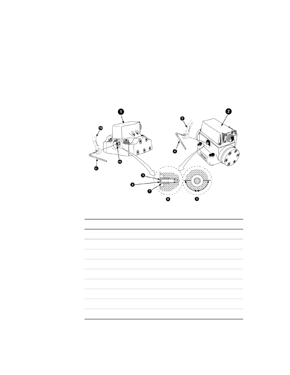
Item Description
1 Series 252.2X, 252.4X, and 252.5X Servovalves
2 Series 252.3X Servovalve
3 3/8 Inch
4 3/32 Inch
5 Base (end view)
6 Base (side view)
7 Self Locking Nut
8 Scribe Mark on Adjuster Pin Pointing Toward Servovalve Base
9 Adjustor Pin
Mechanical Null Adjustor Pin