Introduction
MTS Landmark™ Tabletop Load Units - Product Information 37
Item Component Description
11 Servovalves Control both the amount and the direction of fluid entering the
actuator using a high response valve. They determine how
fast the actuator can move. A servovalve is required for each
actuator.
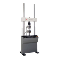
12 Linear actuator Applies axial forces to specimens. The actuator is a
hydraulically powered device that provides linear
displacement of (or forces into) a specimen. Grips and
fixtures can be mounted to the actuator.
13 Control panel
Grip controls
Crosshead lift control
Emergency stop
The Emergency Stop button is standard; the other controls
are optional.
Clamp and unclamp hydraulically controlled grips during
specimen installation and removal.
Controls the crosshead lifts to raise and lower the crosshead
hydraulically.
Removes hydraulic pressure from the load unit and issues an
interlock signal to the controller to stop the test program.