Introduction
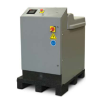
18 Series 505G2 SilentFlo™ Hydraulic Power Unit
Item Component Description
19 Hazard placards Hazard placards contain specific safety information and are
affixed directly to the system so they are plainly visible. Each
placard describes a product-related hazard. When possible,
international symbols (icons) are used to graphically indicate
the type of hazard and the placard label indicates its severity.
The hazard placards are located on the front panel of the
electrical enclosure (item 5).
20 User Interface Panel Controls the operation of the HPU and indicates the current
status of several detectors. Also used for HPU setup. The
user interface panel is located on the front panel of the
electrical enclosure (item 5).
21 Nameplate Provides basic product information such as model number,
serial number, and electrical information. The nameplate is
located on the electrical enclosure (item 5).
Functional Description
Pump
A variable volume pump draws hydraulic fluid from the reservoir and pressurizes it to the adjusted
output pressure, typically 21 MPa (3000 psi). A check valve prevents hydraulic fluid from being
siphoned back into the reservoir. The pressurized fluid is controlled by a control manifold that contains
the high/low pressure solenoid valve and a non-adjustable relief valve set at 22.4 MPa (3250psi).
Pressure
The start/low/high switch on the front panel of the electrical enclosure controls the hydraulic pressure
of the HPU. The start/low/high switch operates like an automotive ignition switch; turn and hold the
switch in the start position until the motor starts running. The switch returns to the low position.
The unit automatically starts in low pressure to reduce the amperage needed for starting, which will
extend pump and motor life. When operating at this setting, low-pressure fluid is available to the
hydraulic circuit. Low pressure is achieved by diverting a portion of the hydraulic fluid through the high
pressure solenoid and returning it to the reservoir. Selecting high pressure blocks the low pressure
return path and makes all of the pressurized hydraulic fluid available to the hydraulic circuit.
The output pressure can be adjusted from about 1 MPa (145 psi) to 21 MPa (3000 psi). The HPU is
designed to provide 21 MPa (3000 psi). A nonadjustable relief valve is set at 22MPa (3190 psi) to
protect the hydraulic system from excessive pressure.
Filtering
As hydraulic fluid returns to the reservoir, it is filtered by a 3-micron element. This ensures that all
hydraulic fluid is filtered whether it travels out through the circuit or returns by way of the unit’s control
manifold under low pressure. Filter cleanliness is automatically monitored. An indicator lights on the
front panel signaling when the filter needs an element change.
 Loading...