Installation
Series 505G2 SilentFlo™ Hydraulic Power Unit 33
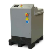
B. Connect the grounding wire to the lug labeled PE GND (protective earth ground).
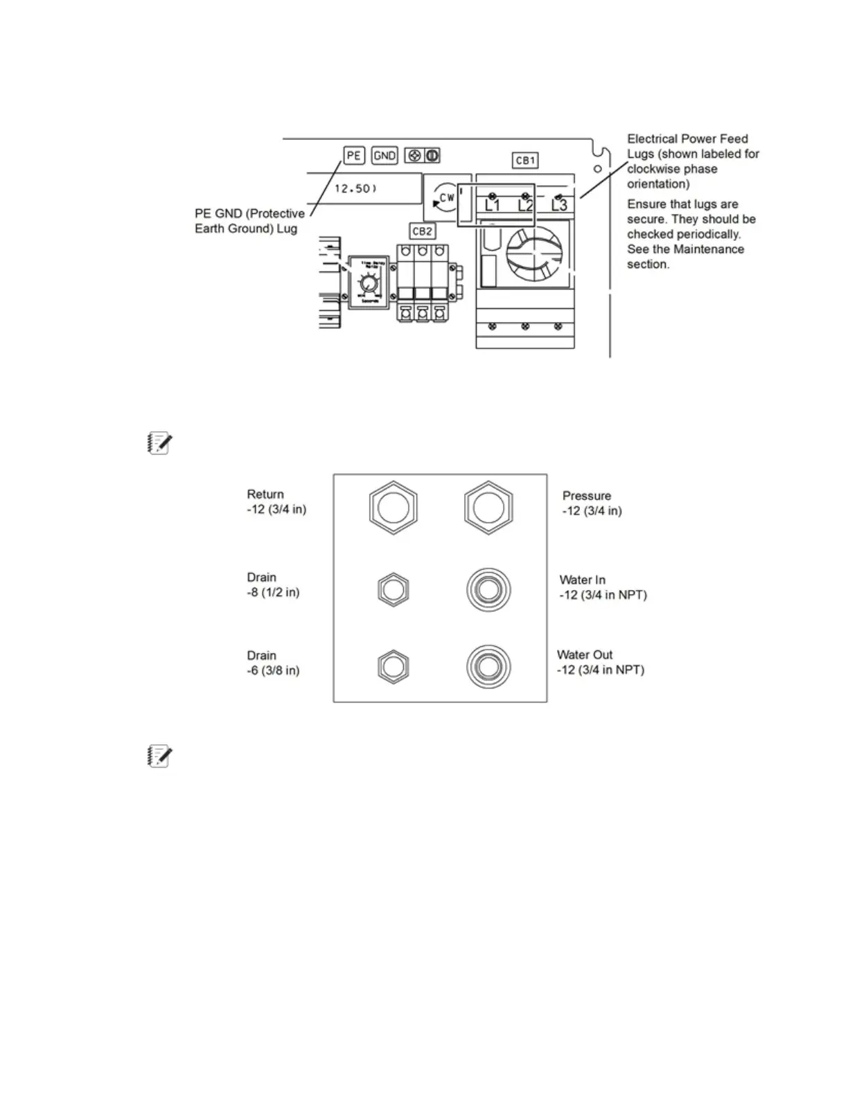
3. Connect the hydraulic lines.
The following figure shows the hydraulic adapter ports to the HPU.
Note: Each hydraulic connection requires an O-ring face seal.
4. Connect the water lines.
Note: For hydraulic connections to air-cooled units, refer to the Air-Cooler to
SilentFlo™ HPU Integration Product Information manual (MTS part number 100-135-
073).
The HPU requires connection to a suitable water supply, equipped with an appropriate shutoff
valve, to cool the hydraulic fluid. The differential pressure required between the HPU water
inlet and outlet connections is 0.24 to 0.34 MPa (35 to 50 psi). The maximum allowable water
inlet pressure is 0.83 MPa (120 psi).
The water supply must also be capable of maintaining water flow at a rate listed in the
following table.
 Loading...