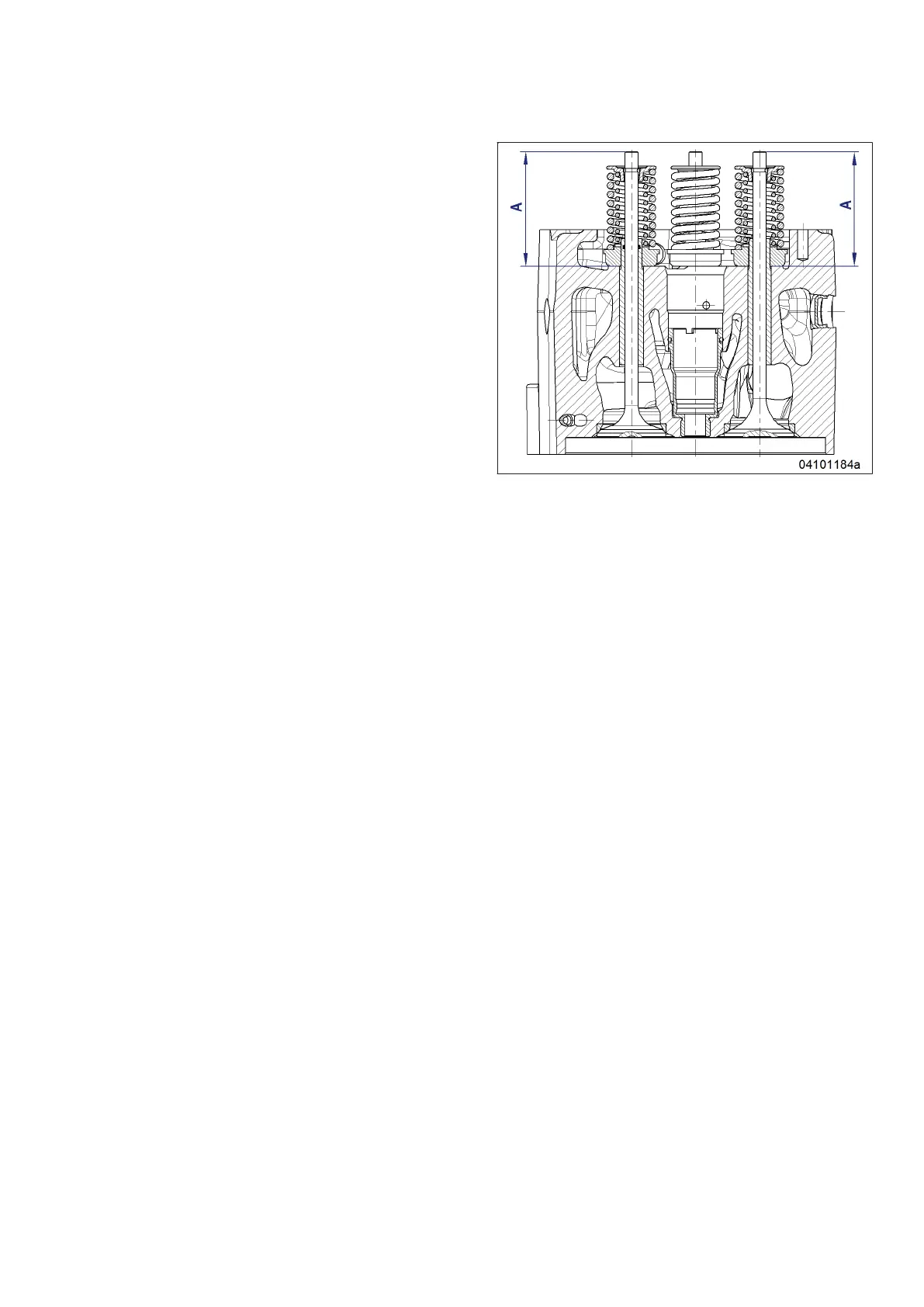
4. Measure distance between valve stem end
and cylinder head top at the injector bore
with depth gage (see figure).
• Specified value for a new cylinder
head: 93.8 mm.
• Admissible wear: 2 mm.
• If the measured value is > 95.8 mm, have
the relevant cylinder head replaced by
specialist personnel ahead of schedule.
5. Install valve bridge.
6. Adjusting valve clearance (→ Page 90)
Final steps
1. Remove barring tool (→ Page 75).
2. Install injector (→ Page 97).
3. Install cylinder-head cover upper section (→ Page 94).
MS150049/04E 2017-04 | Valve Drive | 89
TIM-ID: 0000070354 - 001
 Loading...