Do you have a question about the MTX Thunder6500D and is the answer not in the manual?
Welcome message and highlights MTX's leadership in audio amplifiers.
Guidance on effectively using the owner's manual for installation and operation.
Provides MTX contact details for inquiries and support.
Details advanced technologies like ISMT, PWM MOSFET, Class D, and protection circuits.
Lists RMS power, dynamic power, SNR, damping factor, frequency response, crossover, and dimensions.
Lists RMS power, dynamic power, SNR, damping factor, frequency response, crossover, and dimensions.
Lists RMS power, dynamic power, SNR, damping factor, frequency response, crossover, and dimensions.
Used to match amplifier input sensitivity to the source unit's output.
Enhances low-frequency response with adjustable bass boost up to 18dB.
Adjustable crossover frequency from 40Hz to 200Hz at 24dB/octave.
Accepts line-level or speaker-level RCA inputs up to 8Vrms.
Allows remote bass adjustment from the driver's seat for multiple amplifiers.
Provides RCA outputs for daisy-chaining additional amplifiers.
Enables operation with source units having speaker-level outputs.
Prevents clipping at high SPL levels; switchable on/off for SPL competitions.
Diagram showing input and control layout for the THUNDER4250D amplifier.
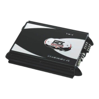
Diagram showing input and control layout for the THUNDER6500D amplifier.
Diagram showing input and control layout for the THUNDER81000D amplifier.
Details on amplifier fuses, their ratings, and necessary precautions.
Instructions for connecting the main 12V+ power source to the amplifier.
Explains the function of the remote turn-on wire for amplifier operation.
Guidance on establishing a proper and secure ground connection.
Indicates power status and potential overheating conditions.
Connection points for speakers, specifying minimum impedance.
Diagram illustrating the output and terminal layout for the THUNDER4250D.
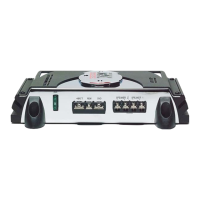
Diagram illustrating the output and terminal layout for the THUNDER6500D.
Diagram illustrating the output and terminal layout for the THUNDER81000D.
Step-by-step guide to calibrate amplifier gain to the source unit's output.
Explains impedance requirements for mono amplifier speaker configurations.
Explanation of electrical filters dividing frequency ranges for speakers.
Defines impedance, line level, speaker level, and signal types in audio systems.
Diagnosing issues when the amplifier's LED does not illuminate.
Troubleshooting steps for when the amplifier powers on but produces no sound.
Identifying causes and solutions for distorted audio output.
Resolving issues with reversed stereo balance.
Diagnosing and fixing boomy or weak bass response.
Troubleshooting frequent fuse blowing issues.
Details three-year warranty for US purchases, conditions, and exclusions.
Explains requirements for making a warranty claim, including proof of purchase.
Provides phone numbers, address, and website for warranty support.
Illustrates connecting RCA inputs and remote turn-on wire from car stereo to amplifier.
Lists essential tools required for amplifier installation.
Shows how to connect speakers, ground, and power terminals for the amplifier.
Specifies wire gauge and highlights vehicle upgrades for high current draw.
| Channels | 1 |
|---|---|
| Frequency Response | 20Hz - 200Hz |
| THD at Rated RMS Power | <1% |
| Bass Boost Frequency | 40Hz |
| Low-Pass Crossover | 40Hz - 200Hz |
| Subsonic Filter | 20Hz |
| Phase Shift | 0 - 180 degrees |
| RMS Power at 2 Ohms | 1000W |
| RMS Power at 1 Ohm | 1500W |
| Input Voltage | 12V |
| Bass Boost | 0-18dB @ 40Hz |