11
6.3 Model type selection
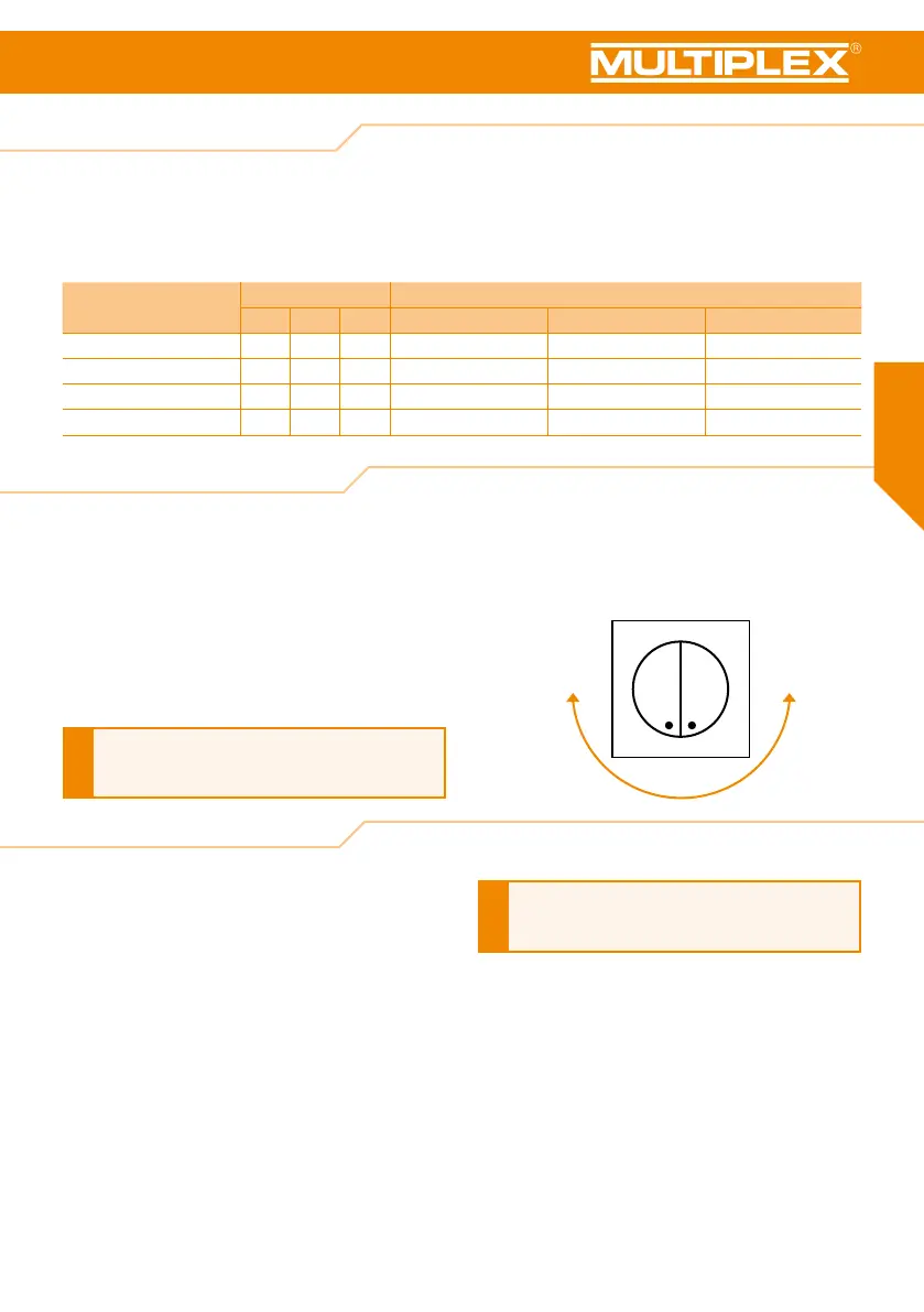
6.4 Gyro gain adjustment
6.5 3-way switch setting
100% 0%
MULTIGyro G3 uses a 3-bit jumper (J 1-2-3) for model type
selection. Adapt the adjustments J1, J2 and J3 as specied
in the table according to your type of aircraft. "0" equals open
and "1" closed, i.e. for the selected type.
Jumper setting upon delivery: "Standard" for standard aircraft
model. After altering the jumper setting, switch the MULTIGyro
G3 off and on to activate the selected type of aircraft.
Model type Jumper setting Servo connection
J1 J2 J3 OUT-1 OUT-2 OUT-3
Gyro off 0 0 0 - - -
Standard aircraft 0 0 1 Aileron servo Elevator servo Rudder servo
Delta wing or ying wing 0 1 0
Left wing servo
Right wing servo
Rudder servo
Aircraft with a V-tail 1 0 0 Aileron servo Left tail servo
Right tail servo
MULTIGyro G3 provides three trimming potentiometers to
adjust the gyro gain of the aileron, the elevator and the rudder
separately. Use a suitable screwdriver for this task. Increase
the gyro gain by turning the potentiometer clockwise. Decrease
the gyro gain by turning the potentiometer anticlockwise. The
ideal volume setting is determined by various factors. These
include, for instance, the size of the fuselage, the weight of
your model or, if necessary, the power allocation used and the
size of the rudder surfaces.
We strongly suggest adjusting the gain to a lower volume
for the initial ight. The adjustment is immediately active –
without the need for a restart. Finely adjust the potentiometer
for subsequent ights, as required.
When carrying out adjustments, always disassemble
the propeller
or disconnect the drive motors from the
ight control system.
!
Dene a 3-way switch at your transmitter. The channel for
the 3-way switch from the receiver is connected to pin 1:
ight mode changeover switch "IN". Use this 3-way switch
to change the ight mode while the aircraft is airborne.
If the “Channel switch” slot has not been assigned, Standard
mode is selected as default. However, this is not recommended,
as it is then impossible to switch off the gyro
and a malfunction
could cause your model to crash,
particularly if the gyro in the
model moves from its dened
position.
When using a 2-way switch, you can toggle between
two of the three available modes. These modes differ
according to the type of transmitter.
i
When MULTIGyro G3 is in operation, the current flight mode
is indicated by the illuminated LEDs:
· Standard mode: blue LED illuminated
· Heading hold mode: red LED illuminated
· Gyro off (gyro system deactivated): no LED illuminated