SETTING UP AND CONFIGURING THE DEVICE
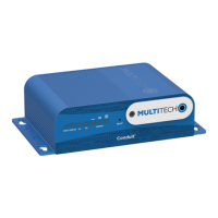
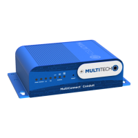
Conduit
®
Cat 4 for EU/UK MTCDT-L4E1 Hardware Guide 17
Accessory Port (mCard) Interfaces
The accessory card interface on the Conduit base board has the following interface options:
Interface Description
I2C Used by all accessory cards. I2C is required for
Electronic Identification (EID) support on the accessory
card but can be used for other I2C devices. It should
supports standard (100 kHz) and/or fast (400 kHz) clock
speeds.
The I2C interface reserves the full block of EEPROM
address space for Electronic ID support, so we
recommend that you not attach any other EEPROM
devices to the interface. We recommend that you use a
24C04 part, because both address bits of the 24C04 are
connected to the AP interface allowing you to identify
four separate accessory port (AP) cards in a system.
Serial UART Serial UART with HW flow control used by Serial
inteface based Accessory Cards
SDIO interface and/or SPI Interface AP1 has option for SDIO or SPI interface, based on what
Accessory Card is installed. AP2 supports only SPI based
Accessory Cards.
GPIO Additional control pins for certain Accessory Cards.
Interrupts Software defined interrupts. Can also be used as
additional control pins.
PPS GPS generated Pulse-Per-Second signal used for
software timing. Default is 1 pulse/sec.
USB 2.0 A standard USB 2.0 High Speed interface for USB based
Accessory Cards.
5 VDC 1 Amp supply Used by all accessory cards.
3.3 VDC 1 Amp supply Used by all accessory cards.
For accessory card specifications, regulatory content, and installation information, see the Accessory Card
information.
Installing a Micro SD Card
You need:
Phillips screwdriver
MicroSD memory card
To install or replace the SD card:
1. Disconnect power to the Conduit, if it is connected.
2. At the front of the Conduit, remove the screw that secures the MultiTech nameplate.
3. Locate the SD card at the left side of the opening on the underside of the PC board.