DehumidierML420-MLT1400
500
700
900
1100
1300
1500
20
0
40
60
80
100
120
F5
F7
400
Pa
m
3
/h
M 5
F7
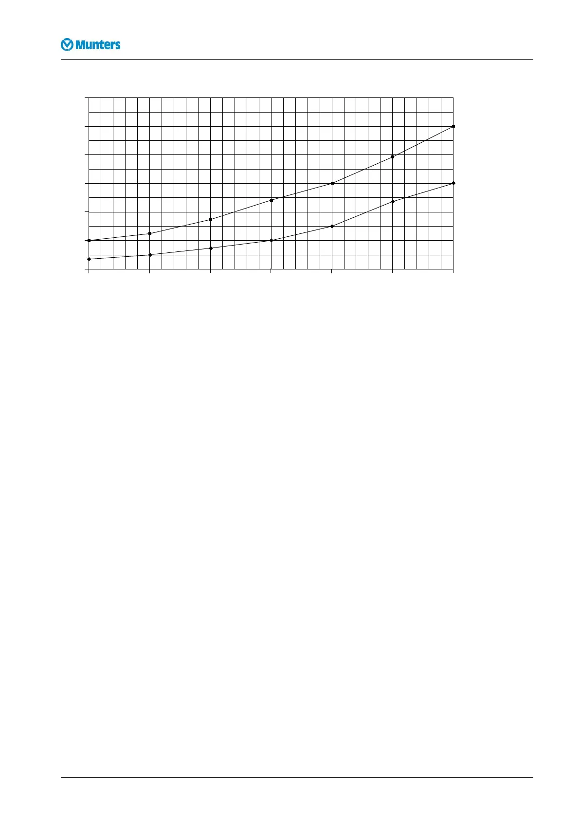
Figure1.1Pressuredrop,lterinthelterbox
NOTE!Thepressuredropforthereactivationsideisnotshownonthediagramsincethevaluesaresosmallthat
theydonotaffecttheperformanceoftheunit.
1.6Humiditycontrolsystem
1.6.1Introduction
MuntersRH98andVariDryarehumiditycontrolsystemsintendedforusewithMuntersdehumidiers.
Theycontroltheairhumiditybyregulatingthepowertotheunitreactivationheater.
Thesystemcomprisesahumiditytransmitterandacontrolunit.Thehumiditytransmitterisatruetwo
wiretransmitter,whichispositionedwheretheairhumidityistobecontrolled,eitherintherelevantroom
orintheairduct.
Thecontrolunitsendscontrolsignalstothedehumidier.Thepowercontrolisperformedinoneortwo
steps.
Thesystemhasapotentialfreecontacttowhichanexternalalarmdevicecanbeconnected.
1.6.2Transmitter
Thehumiditytransmittersareavailableintwodifferenttypes,wallorductmounted.
Thehumiditytransmittersensoremitsasignalproportionaltotheairhumidity.
Thesignalisampliedandsenttothecontrolunitbycable.
Thehumiditytransmittersensorissensitiveandmustbehandledwithcare.
1.6.3Controlunit
Thecontrolunitcontainsacontroller,whichreceivesthesignalfromthehumiditytransmitter.The
controllerthensendsacontrolsignaltothedehumidierwhichdeterminesthereactivationheateroutput.
42Options190TGB-1035-H1604
 Loading...