DehumidierML180-MLT350
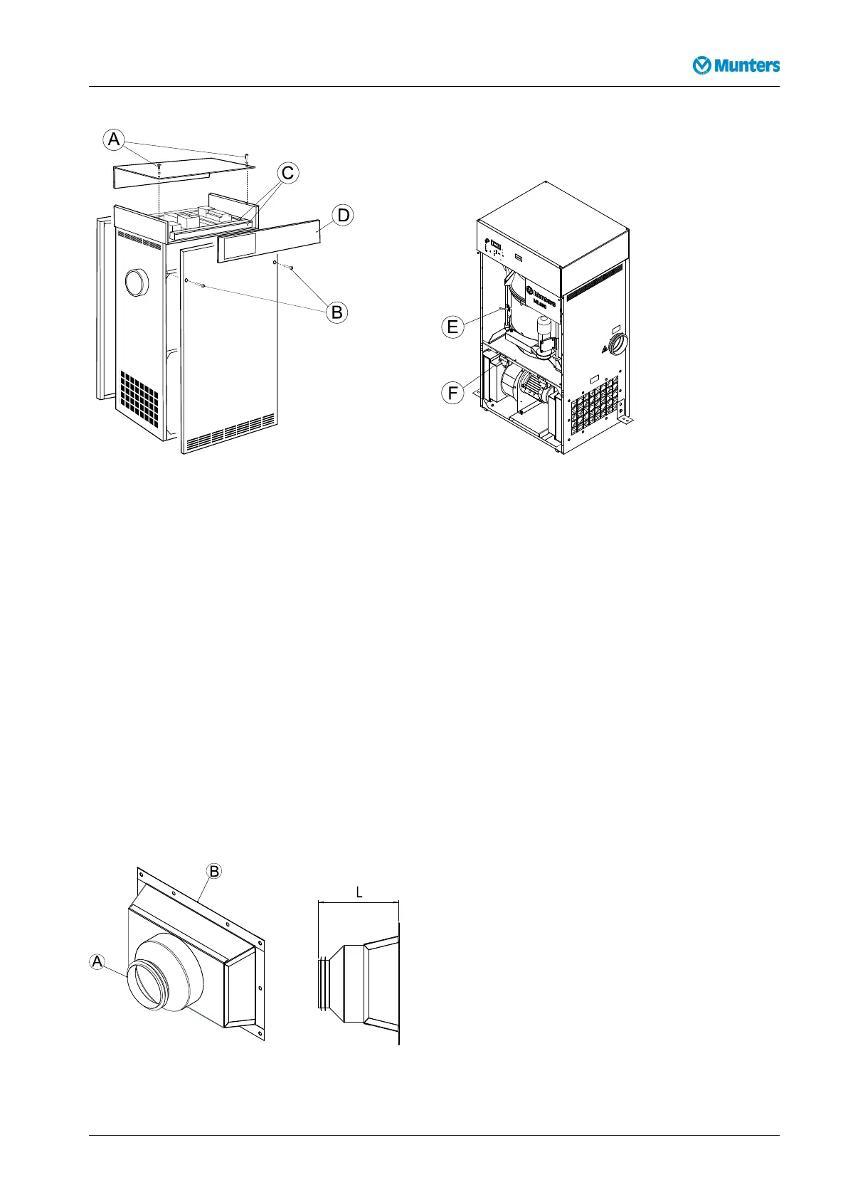
Figure4.2Changingpanelpositions
1.Removethetwobolts(B)securingthefrontpanelandcarefullyremovethepanel.
2.Removethetwoboltssecuringtherearpanelandcarefullyremovethepanel.
3.Removethetwobolts(A)andwasherssecuringthecontrolandtoppanels,thencarefullyremovethe
toppanel.
4.Removethecableductcovers(C),re-routethecablesandtthecontrolpanel(D)ontotheoppositeside
oftheunit.Retthecableductcovers.
5.Fitthefront,rearandtoppanelsintheirnewpositions.
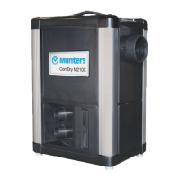
4.5Ductinstallation
4.5.1Generalrecommendations
Theconnectionsforprocessandreactivationairaredesignedinaccordancewiththerecommendationsin
ISO13351.TherectangularductconnectionscontaintappedinsertsforM8screws.
Figure4.3Ductconnections
190TGB-1034-L1604Installation9