DehumidierML420-MLT1400
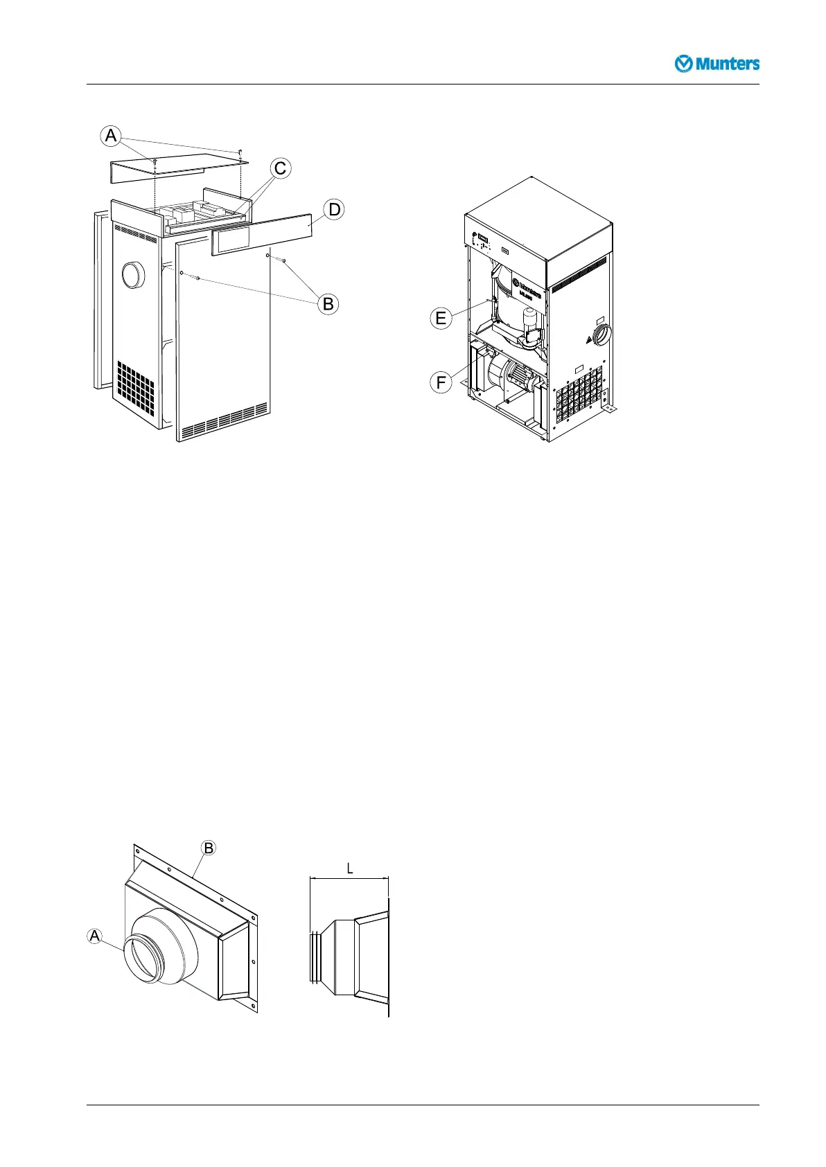
Figure4.2ChangingpanelpositionsFigure4.3Rotorstop(E)andltermonitors(F)
1.Removethetwobolts(B)securingthefrontpanelandcarefullyremovethepanel.
2.Removethetwoboltssecuringtherearpanelandcarefullyremovethepanel.
3.Removethetwobolts(A)andwasherssecuringthecontrolandtoppanels,thencarefullyremovethe
toppanel.
4.Removethecableductcovers(C),re-routethecablesandtthecontrolpanel(D)ontotheoppositeside
oftheunit.Retthecableductcovers.
5.Loosentherotorstop(E)andthetwoltermonitors(F).Removethecableties.
6.Fittherotorstopandltermonitorsontheoppositesideoftheunit.Tiethecables.
7.Fitthefront,rearandtoppanelsintheirnewpositions.
4.5Ductinstallation
4.5.1Generalrecommendations
Theconnectionsforprocessandreactivationairaredesignedinaccordancewiththerecommendationsin
ISO13351.TherectangularductconnectionscontaintappedinsertsforM8screws.
Figure4.4Ductconnections
190TGB-1035-H1604Installation9