33 | © Munters AB, 2019
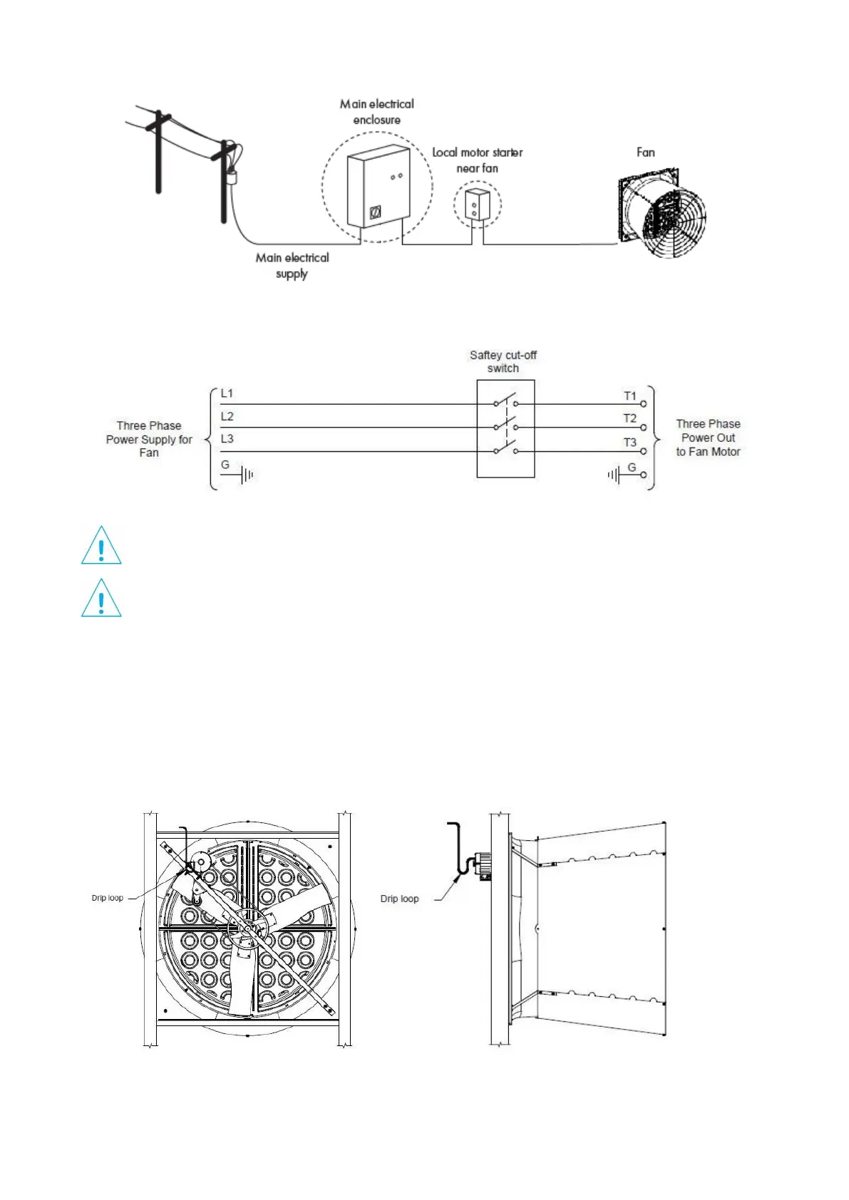
Below are suggested wiring diagrams for connecting the fan to the mains electrical supply. These diagrams are however
subject to local laws and regulations and should be modified if necessary to comply with such laws and regulations.
NOTE
Failure to operate the fan with an overload protection device will render the motor guarantee null and void.
Such motor overload protection devices can be ordered from Munters and be supplied with the fans.
NOTE
The connection cable must be completely extracted from the fan housing in order to avoid being damaged
by moving parts.
To avoid excessive voltage drop, which can be harmful to electrical motors, care must be taken as to the thickness of
cables used as well as the distance from the main electrical enclosure to the motor. Proceed as follows:
• check that the data shown on the plate correspond to the connection data;
• before connecting the device, make sure that the supply voltage matches the device voltage;
• use only cables suitable for the current intensity indicated on the identification plate of the device.
For the sizing of the section, follow the sizing principles imposed by the EN 61800-5-1 standard. The protective conductor
must have at least the same section as the external conductor.
As the power cable exits the back of the motor form a drip loop and then run cable to power source. See Figure 29A and
29B.
Figure 29A Figure 29B