2202MYJE-MY-C8-N_2018.02.
Chapter 5 Maintenance and Inspection
Compound 2-stage Screw Compressor 3225**C 5.5 Reassembly
5-54
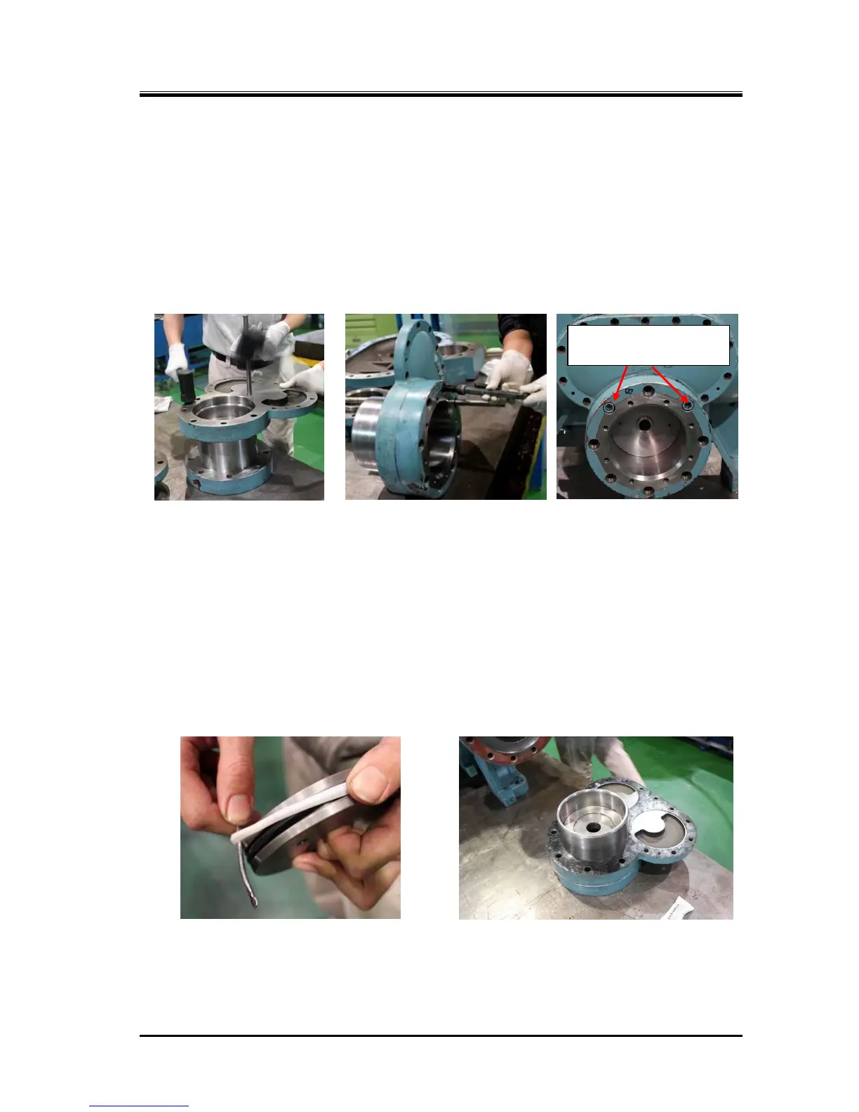
e) Align the position of the balance piston cover with the unloader cylinder. As shown in the above
Photo 090, using a steel rod for positioning makes it easier to align the position of bolt holes.
As no gasket is used on the mating flange between the balance piston cover and unloader cylinder,
evenly and thinly apply liquid gasket (made of special synthetic rubber) on the surface of the flange
of the unloader cylinder inside from the center of the bolt holes.
f) As the O-ring of the balance piston cover is already installed, lightly tap the flange surface with a
soft hammer to install it as shown in Photo 091.
g) When joining the flanges, also align the bolt hole positions if any positioning steel rod is not used.
Then, insert two hexagon socket head cap screws [61] in the positions shown in Photos 092 and
093 to fasten the unloader cylinder to the balance piston cover.
h) Install the O-ring [73-2] in the O-ring groove on the tip of the unloader push rod [67-2], at the
position where the unloader piston is installed.
i) Attach the O-ring [65-2] without lubricating oil on the unloader piston [64-2], and then install the cap
seal [66-2] on it. It can be smoothly installed by slightly folding the cap seal along the circumferential
direction. Also, using a small and smooth spatula (Photo 094) will facilitate the assembling work.
j) Install the unloader piston fitted with the O-ring and cap seal in the unloader cylinder. One side of
the unloader piston is with screw holes for eye bolts, while the other side does not have such holes.
First, to make it easier to fit the cap seal on the unloader cylinder wall, lightly press one side of the
piston onto the chamfered area of the unloader cylinder by hand, changing the side of the piston for
several times. Finally, apply lubricating oil to the unloader cylinder, then, push and install the piston
with the screw holes side of the piston facing the unloader cover. After the installation, check that
the cap seal is not broken or pinched.
k) Push the unloader piston into the unloader cylinder and set it in the middle of the cylinder, pull the
unloader push rod [67-2] toward you, and install the balance piston cover with the gasket fitted as
shown in Photo 095 onto the high-stage suction cover (Photo 096). Pushing the piston into the push
rod and temporarily fastening the lock nut [69-2] in the course of the work will make later work
easier.
Bolt positions for fastening
the cylinder and cover

 Loading...