2202MYJE-MY-C8-N_2018.02.
Chapter 5 Maintenance and Inspection
Compound 2-stage Screw Compressor 3225**C 5.5 Reassembly
5-60
5.5.12 Low-stage Unloader Cylinder
The installation of the low-stage unloader cylinder may be done either after the bearing cover
installation described in Section 5.5.10 or after the installation of the mechanical seal.
a) Check that the O-ring [73-1] is inserted in the O-ring groove on the tip of the unloader push rod
[67-1], at the position where the unloader piston is installed.
b) Install the O-ring [65-1] and cap seal [66-1] on the unloader piston [64-1].
c) Install the unloader piston fitted with the O-ring and cap seal in the unloader cylinder [60-1]. The
work procedure is the same as that for the high-stage side as described in Section 5.5.9, item j).
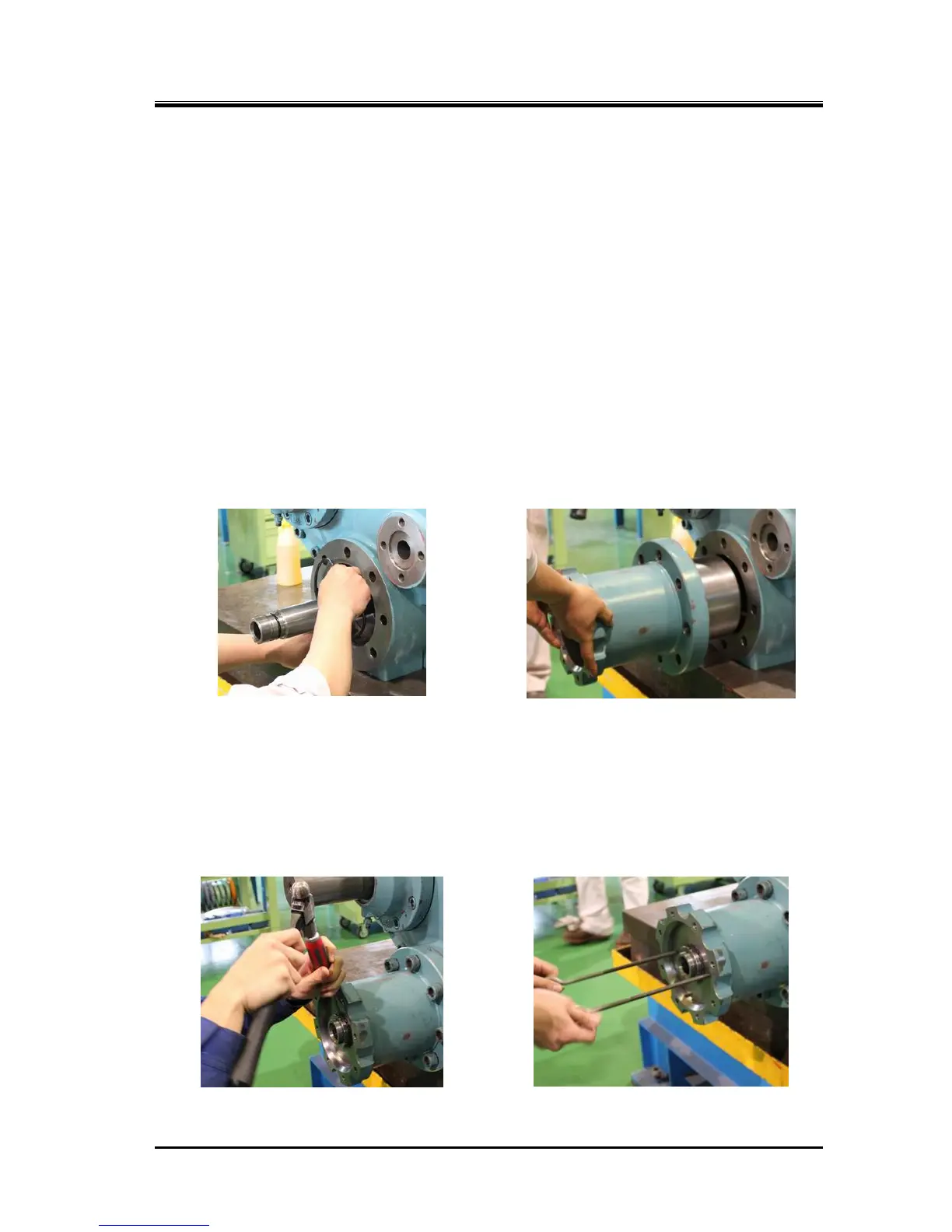
d) Insert the O-ring [63-1] in the O-ring groove on the part of the bearing cover [16] in which the
unloader cylinder is installed (Photo 115).
◆ The assembly method of this O-ring [63-1] has been changed in the design change dated Oct.
29, 1996. While the O-ring is inserted to the triangular part on the flange surface of the bearing
cover that makes contact with the unloader cylinder in the previous method, the O-ring is
inserted in the O-ring groove in the current method.
e) Install the unloader cylinder in the bearing cover (Photo 116), and fasten the eight hexagon socket
head cap screws [62-1] at the specified tightening torque of 450 N・m.
f) Set the lock washer [70-1] and lock nut [69-1] on the unloader push rod, and fasten the lock nut at
the specified torque of 180 N・m.
At this point, in the case of 3225M*C, be careful not to excessively pull the unloader piston toward
you as it is explained in the caution in the next section.
To prevent loosening, bend the tooth of the lock washer on the tightening side at the notch of the
lock nut (Photo 117). Lastly, use the eye bolts to check the movement of the unloader piston (Photo
118).

 Loading...