2202MYJE-MY-C8-N_2018.02.
Chapter 5 Maintenance and Inspection
Compound 2-stage Screw Compressor 3225**C 5.4 Disassembly and Inspection
5-37
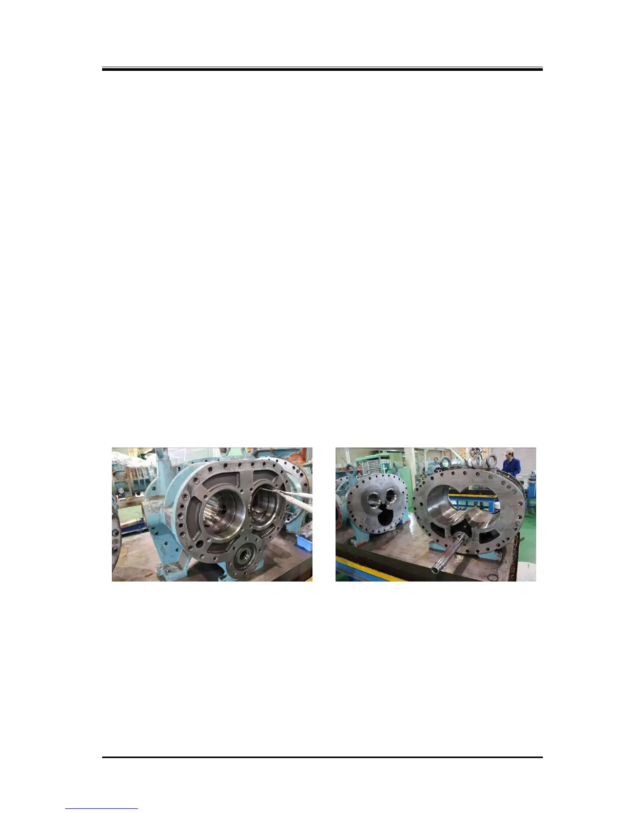
b) Check the condition of the surface of the bearing head on the rotor side, where the discharge port is.
Properly mend the surface if any flaw is observed. If the entire surface has significant flaws, either
the thrust bearing is defective or the end clearance adjustment is poor.
If oil compression has been caused during the operation, carefully and thoroughly check the area of
the discharge port in particular. If the continued use is in doubt at all, perform the penetrant testing
(color check) to determine if it can be used or not.
c) With the unloader slide valve mounted in position, check the step height between the slide valve
and the main rotor casing surfaces. Usually, the surface of the slide valve should be lower than the
surface of the main rotor casing.
If the top surface of the slide valve has a trace of hitting the rotor, the probable cause is that the slide
valve is worn or the rotor shaft/bearing is worn. Please contact our sales offices or service centers.
d) Check the properness of the slotted guide pin [68-2] at the tip of the unloader push rod [67-2] that
engages with the indicator cam [77-2].
5.4.16 Low-stage Bearing Head and Main Bearings
5.4.16.1 Disassembly
a) Unscrew and remove all the hexagon socket head cap screws [2-1].
b) Drive in the alignment pins [3-1] from the bearing head side to the main rotor casing side.
c) Use the jacking screw holes on the flange to separate the bearing head and the main rotor casing.
d) Separate them carefully along the shaft axis, as the unloader push rod [67-1] is engaged.
e) The main bearing [27-1] can be easily pulled out by removing the snap ring [29-1] and then lightly
tapping it from the rotor side via a pad. Otherwise, use a special tool to pull it out.
f) Remove the slide valve as an assembly, using the same procedure as for the high-stage unit.
Carefully perform the work, as you are handling a heavy object.

 Loading...