2202MYJE-MY-C8-N_2018.02.
Chapter 5 Maintenance and Inspection
Compound 2-stage Screw Compressor 3225**C 5.5 Reassembly
5-53
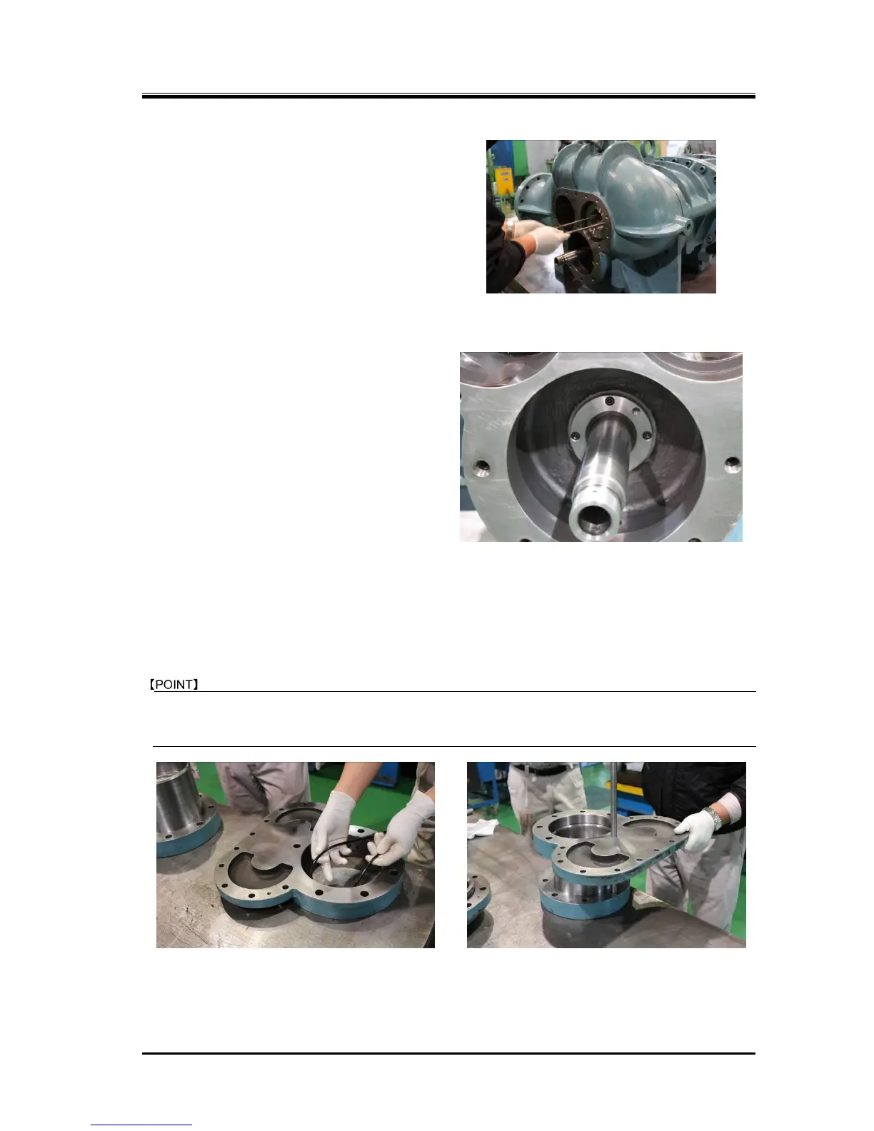
5.5.8.4 Installing the Balance Piston
On the high-stage side, install the balance piston
[30] (Photo 087).
Then, use the external snap ring pliers to install
the snap ring [32], and fix it in position.
Check that the snap ring is fully seated in the
groove.
5.5.9 Balance Piston Cover
and High-stage Unloader Cylinder
a) Before installing the balance piston cover on
the high-stage suction cover [5-2], install the
O-ring [328] in the part of the high-stage
suction cover where the push rod passes
through. Then, use hexagon socket head cap
screws [166-2] to install the O-ring gland
[326-2].
b) Install the unload spacer (for 30% load) [420]
on the high-stage push rod. In the case of
3225*LC, no unloader spacer is used
(because the full length of the unloader
cylinder has been reduced to make
adjustment unnecessary).
c) In the case of 3225**C, as the high-stage side
also has the unloader cylinder [60-2], the
work will become easier if the unloader cylinder is first installed on the balance piston cover [22] and
then the resulting assembly is installed on the high-stage suction cover [5-2].
d) Install the O-ring [63-2] in the O-ring groove on the machined surface of the balance piston cover
along which the unloader cylinder is installed (Photo 089).

 Loading...