2200Q2JE-HO-KHM-N_2015.02.
Chapter 5 Maintenance and Inspection
Ammonia Semi-hermetic Motor with K-series Compressor 5.1 Precautions for Maintenance
5-17
5.4.3 Motor Rotor
a) Motor rotor [607] is a heavy component. In the same way as in the disassembly, prepare the set-up
to lift up the motor rotor by using a chain block and lifting tool (see Section 5.3.8).
Provisionally marking the key slot position on the circumference of the motor rotor shaft will
facilitate the matching with the key on the crankshaft during assembling.
b) Mount the key [4] with the key slot on the compressor crank shaft facing upward.
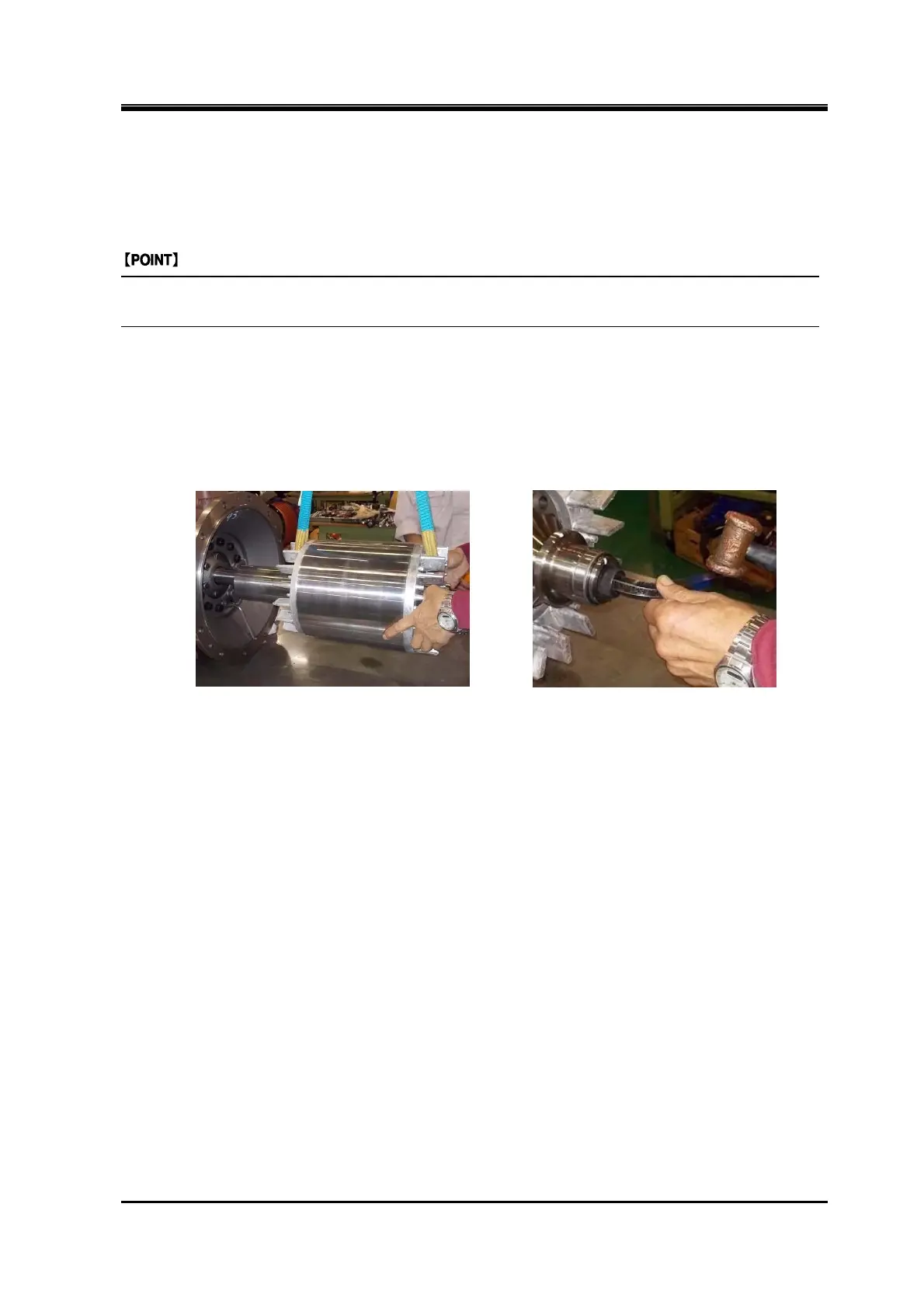
c) While keeping the key slot on the motor rotor shaft facing upward, lift up the motor rotor. While
lifting the motor rotor so that the center of shaft hole matches the center of crank shaft, mount it on
the shaft by pushing the motor rotor (following picture to the left).
d) Tighten the motor rotor with the motor rotor mounting bolt [609] attached with a washer [609-1]
(following picture to the right).
e) If the motor bearing [613] is replaced, fix the inner bearing race on the motor rotor by shrink-fitting.
Heat up the inner bearing race to a temperature of 80 to 100°C by using a bearing heater or the
like to fix it on the motor rotor shaft, and attach the motor bearing snap ring B [613-2].