EasyManua.ls Logo

mycom K Series User Manual

mycom K Series
51 pages
To Next Page IconTo Next Page
To Previous Page IconTo Previous Page
Page #47 background imageLoading...
Page #47 background image
2200Q2JE-HO-KHM-N_2015.02.
Chapter 5 Maintenance and Inspection
Ammonia Semi-hermetic Motor with K-series Compressor 5.1 Precautions for Maintenance
5-20
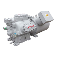
5.4.6 Motor Bearing Retainer
a) Apply oil on the planetary ring of the motor bearing
[613] and the lip part (in contact with the shaft) of the
motor oil seal [617].
b) Screw two stud bolts (safety bolts) into appropriate top
bolt holes.
c) Apply oil on the gasket [615] and attach it to the bearing
retainer [614] so that the bolt holes allow the stud bolt
to enter.
d) While holding the bearing retainer with both hands,
mount it in the motor casing (picture to the right).
Push the motor rotor shaft [607] into the bearing that
has already been mounted in the bearing retainer.
As the shaft is pushed in, the bottom end of the spigot section hits the flange hole in the motor
casing. In that case, further push in the spigot section while bring it up, it can be mounted onto the
flange surface.
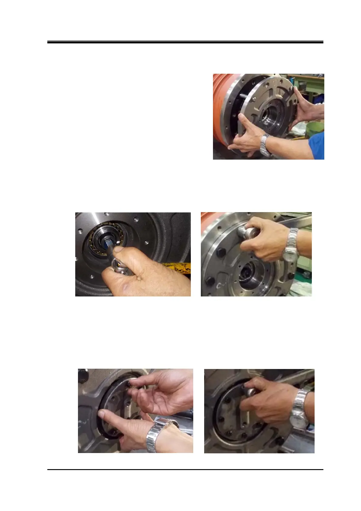
e) After slightly tightening the motor oil seal retainer fastening bolts [619] and fit the hexagonal bar
wrench to the motor rotor mounting bolt [609], ensure that the shaft can be turned by hand
(following picture to the left), tighten them with the specified torque (following picture to the right).
5.4.7 Motor End Cover
a) Apply oil on the gasket [621].
Attach the gasket to the flange of motor end cover [620] while allowing it to the bolt holes.
b) While fitting the motor end cover to the motor bearing retainer (following picture to the left), screw
in the eight bolts [622], and then tighten them with the specified torque (following picture to the
right).

Table of Contents

Question and Answer IconNeed help?

Do you have a question about the mycom K Series and is the answer not in the manual?

mycom K Series Specifications

General IconGeneral
Compression Ratio9.0:1
Ignition SystemCDI
Fuel SystemCarburetor
Engine typeSingle cylinder, 4-stroke, air-cooled
Displacement124cc
Fuel TypeGasoline

Summary

MYCOM Ammonia Semi-Hermetic Motor with K-Series Compressor Instruction Manual

Preface

Revision History

Details of manual revisions and issue dates.

Warranty and Disclaimer

Warranty

Terms and conditions for product repair or replacement.

Disclaimer of Warranty

Clauses exempting MAYEKAWA from warranty obligations.

Important Information

Intended Use of this Product

Specifies the general purpose and application of the compressor.

Precautions for Safe Use

Outlines essential safety measures and work practices.

About this Manual

Provides information on the manual's scope, limitations, and usage.

Structure of this Manual

Outlines the organization and content of the manual chapters.

Chapter 1 Safety

Strict Requirements and Prohibitions

Lists mandatory rules and actions to follow for safe operation.

Warning Notices in this Manual

Explains the different types of warning symbols and their meanings.

Residual Risks

Identifies potential hazards and necessary precautions.

Safety Devices

Details the safety features and required additional protection.

Chapter 2 Product Specifications and Structure

Overview of This Product

Introduces the K-series ammonia semi-hermetic compressor.

Model Designation of the Compressor

Explains the meaning of the model number components.

Product Specifications

Lists standard technical specifications for the compressors.

Service Limits

Defines operational limits for pressure, temperature, and speed.

Outer Dimensions

Provides physical dimensions for different models.

Structure of Semi-hermetic Motor

Illustrates the internal components of the motor.

Parts Configuration Table

Lists part numbers, names, quantities, and remarks.

Chapter 3 Installation

Safety Precautions during Installation

Highlights critical safety measures before and during installation.

Installation Work

Covers procedures for unpacking, storage, and transportation.

Preparation for Installation

Details requirements for installation space, lighting, and cooling water.

Installation Procedures

Covers unit placement and piping connections.

Chapter 4 Operation of Compressor and System

System Operation and Lubrication

Covers lubricating oil, operation, and shutdown procedures.

Chapter 5 Maintenance and Inspection

Precautions for Maintenance and Inspection

Critical safety measures for maintenance and inspection tasks.

Daily Management and Regular Inspection

Procedures for daily checks and routine inspections.

Overhaul Guidelines

Timing and details for motor and compressor overhauls.

Disassembly Procedures

Steps for taking apart the compressor and motor components.

Reassembly Procedures

Steps for putting the components back together.