iVector S2
Installation manual
iVector S2 • 2022-07-01
US
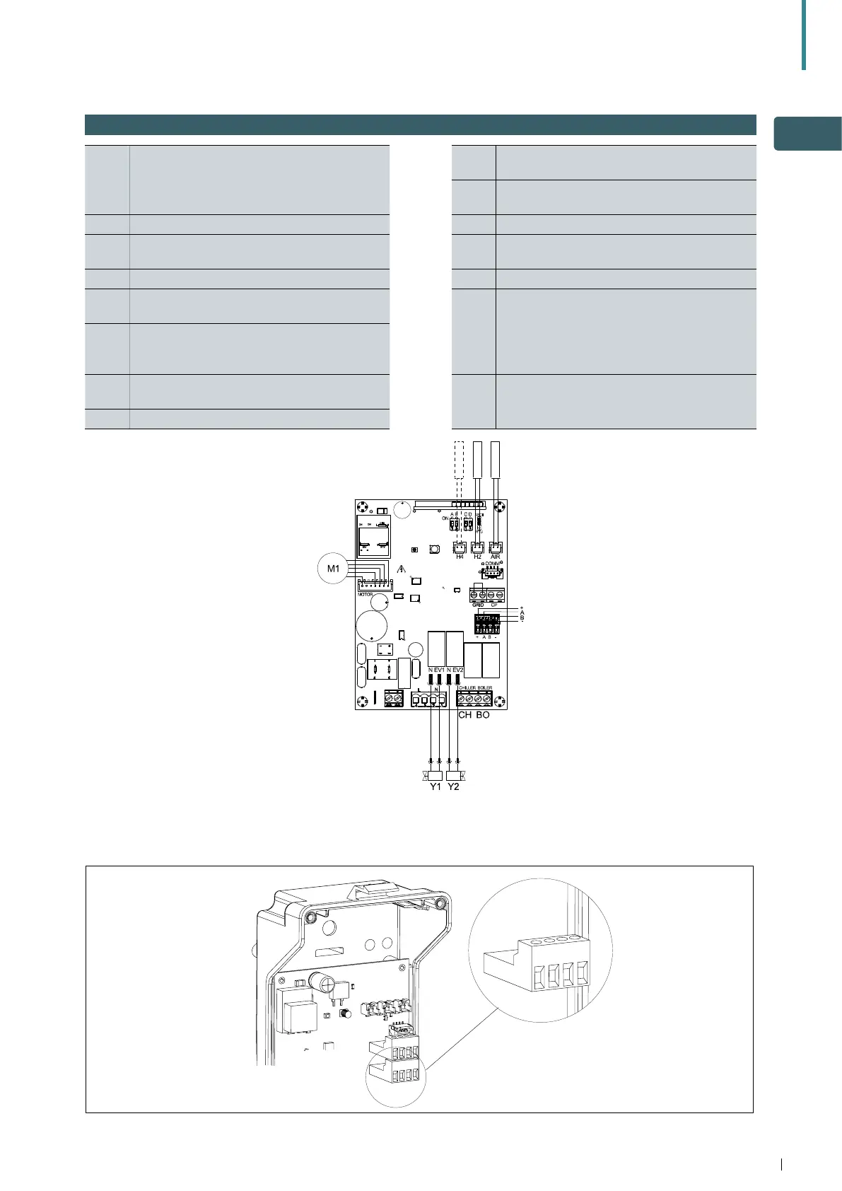
5.5 2 Pipe & 4 pipe models with remote-mounted control
+AB-
serial connection for wall-mounted remote
control (respect AB polarity)
BO
boiler switch output (voltage free contact max
1A)
CH
chiller switch output (voltage free contact
max 1A)
H2* hot water temperature probe (10 k) AIR Air probe optional (**)
H4*
cold water temperature probe (10 k) air
temperature probe (10 k)
M1 DC inverter fan motor
Y1
Valve actuator (230V/ 50Hz 1A output
voltage) (115V/60Hz Canada/US)
* After power on and with the unit is set for
heating or cooling, the fan will only operate
when the water temperature reaches 30°C
(86 °F) in heating, or falls below 20°C (68 °F)
in cooling.
Y2
4 pipe valve actuator or 230V/50Hz 1A output
voltage (115V/60Hz Canada/US)
L-N
230V/50Hz electrical power supply
(115V/60Hz Canada/US)
** Alternatively, connect the air probe to the
remote mounted control
UV UV lamp connection
Electrical connection of the cable from the remote wall-mounted control should be made to the 4-way screw terminal
block (A) on the unit control board. Use suitable cables as detailed in sections 6.2 and 6.3.
A
+
A
B
-