iVector S2
Installation manual
iVector S2 • 2022-07-01
US
0-10V Models
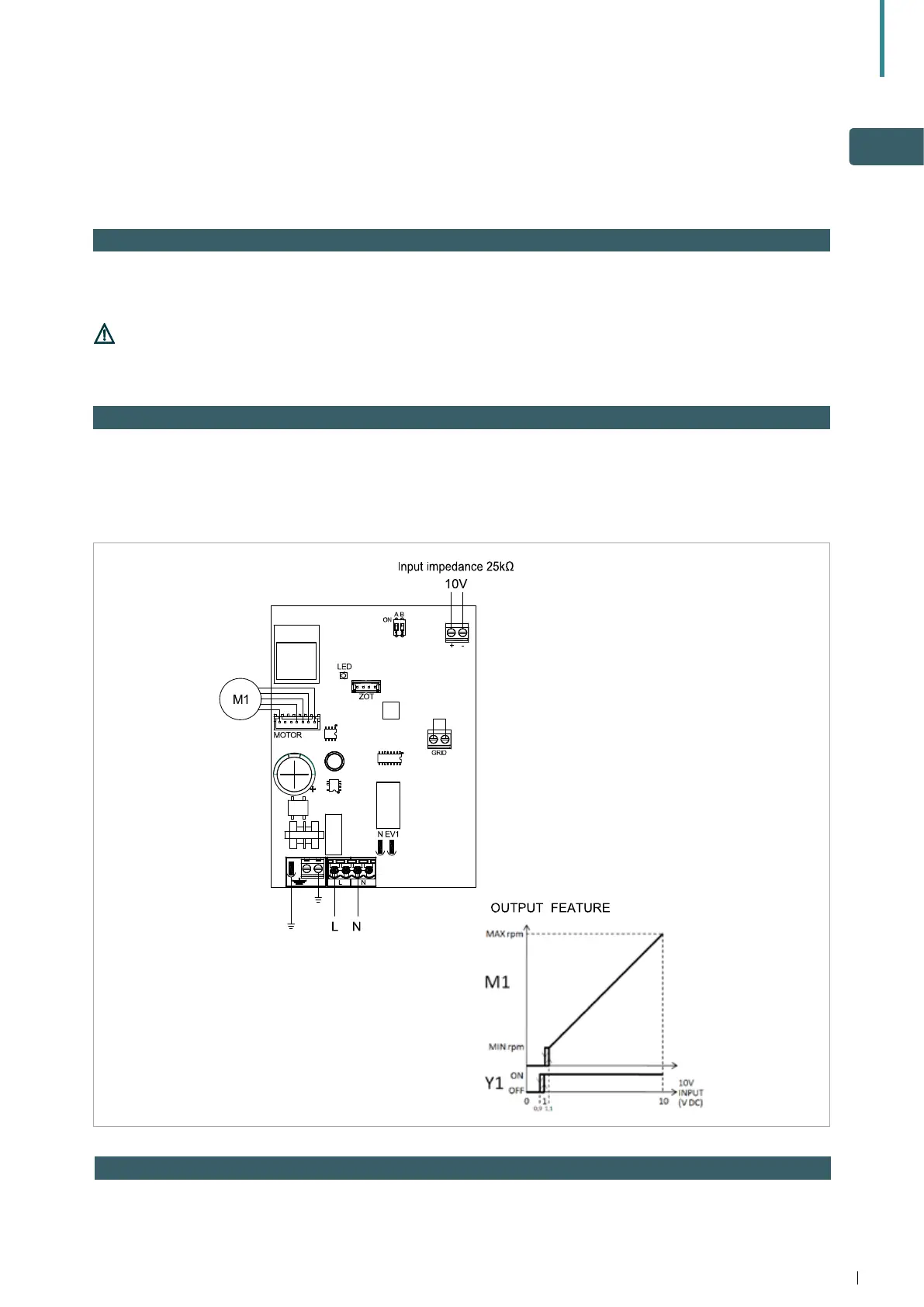
7.2 Connection diagram with 0-10V DC thermostats / signals
Electrical connections for suitable thermostat:
L-N Electrical power supply 230V-50 Hz (115V/60Hz Canada/US) M1 DC inverter fan motor
10V Appliance input 0-10 V
7.3 Fan speed regulation
The speed curve shows linear regulation from the
minimum value (400 rpm) to the maximum value
(1,400 rpm) for voltage values ≥ 1.1V to 10 V DC. The
motor is off when values are lower than 1V DC.
7.1 0-10V fan control
For units with 0-10V fan speed modulation, motor
regulation can be made using an analogue 0-10V DC
input with 25 kΩ impedance.
Valve actuators should be activated from the external
control. If the remote 0-10V thermostat kit is used, a
water temperature sensor is available as an accessory.
Take care to check impedance values ,
especially when controlling more than one unit
in parallel.